Toyota RAV4 (XA40) 2013-2018 Service Manual: Torque converter clutch solenoid circuit
Description
The shift solenoid valve dsl is turned on and off by signals from the ecm to control the hydraulic pressure acting on the lock-up relay valve, which then controls operation of the lock-up clutch.
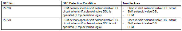
Fail-safe function: if the ecm detects a malfunction, it turns the shift solenoid valve dsl off.
Monitor description
Torque converter lock-up is controlled by the ecm based on engine rpm, engine load, engine temperature, vehicle speed, transmission temperature, and shift position selection. The ecm determines the lock-up status of the torque converter by comparing the engine rpm (ne) to the input rpm (nt). The ecm calculates the actual transmission gear by comparing the input rpm (nt) to the output rpm (sp2).
When conditions are appropriate, the ecm requests "lock-up" by applying control voltage to the shift solenoid valve dsl. When the shift solenoid valve dsl is opened, the shift solenoid valve dsl applies pressure to the lock-up relay valve and locks the torque converter clutch. If the ecm detects an open or short in the shift solenoid valve dsl circuit, the ecm interprets this as a fault in the shift solenoid valve dsl or its circuit. The ecm will illuminate the mil and store a dtc.
Monitor strategy
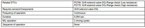
Typical enabling conditions
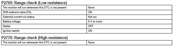
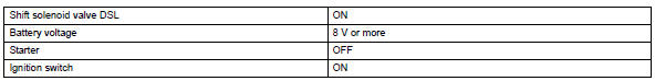
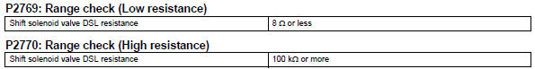
Typical malfunction thresholds
Component operating range
![]()
Wiring diagram
Refer to dtc p0741 (see page ax-62).
Inspection procedure
- Inspect transmission wire (shift solenoid valve dsl)
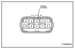
- Disconnect the b27 wire connector.
- Measure the resistance of the transmission wire.
Standard resistance 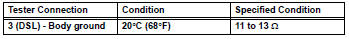


- Check wire harness (transmission wire - ecm)
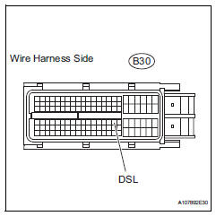
- Disconnect the b30 ecm connector.
- Measure the resistance of the wire harness side connector.
Standard resistance 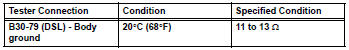

Replace ecm
- Inspect shift solenoid valve dsl
- Remove the shift solenoid valve dsl.
- Measure the resistance between the solenoid valve terminal and solenoid valve body.
Standard resistance:
11 to 13  at 20°c (68°f)
- Connect the battery's positive (+) lead to the terminal of the solenoid valve connector, and the negative (-) lead to the solenoid body. Then check that the valve moves and makes an operating noise.
Ok: valve moves and makes operating noise.


Repair or replace transmission wire
 Pressure control solenoid "d" electrical (shift solenoid valve slt)
Description
Refer to dtc p2714 (see page ax-91).
Monitor description
When an open or short in the shift solenoid valve slt circuit is detected,
the ecm interprets this as a fault.
The ...
 Automatic transaxle fluid
On-vehicle inspection
Check transaxle fluid level
Hint:
Drive the vehicle so that the engine and transaxle are at
normal operating temperature.
Fluid temperature:
70 to 80°c (158 to 176°f ...
Other materials:
Headlight switch
The headlights can be operated
manually or automatically.
Turning on the headlights
Operating the switch
turns on the lights as follows:
U.S.A. (Type A)
The side marker, parking,
tail, license plate, instrument
panel lights, and
daytime running lights turn on.
The headlights and all
light ...
If you have a flat tire
Your vehicle is equipped with a spare tire. The flat tire can be
replaced with the spare tire.
WARNING
â– If you have a flat tire
Do not continue driving with a flat tire.
Driving even a short distance with a flat tire can damage the tire and the
wheel beyond repair, which could result in an accide ...
Curtain shield airbag assembly
Components
On-vehicle inspection
Check curtain shield airbag assembly (vehicle not involved in
collision)
Perform a diagnostic system check (see page rs-
49).
With the curtain shield airbag assembly installed on
the vehicle, perform a visual check. If any of the
defects ...
