Toyota RAV4 (XA40) 2013-2018 Service Manual: Transmission control cable assembly
Replacement
- Remove rear console box sub-assembly
- Remove the console box (see page ip-20).
- Disconnect cable from negative battery terminal
Caution:
Wait at least 90 seconds after disconnecting the cable from the negative (-) battery terminal to prevent airbag and seat belt pretensioner activation.
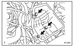
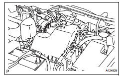
- Remove battery
- Loosen the nut and remove the bolt and battery clamp.
- Remove the battery.
- Remove the battery tray.
- Remove the 4 bolts and battery carrier.
- Remove the 2 bolts and battery bracket reinforcement.
- Remove air cleaner assembly
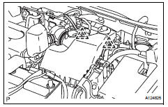
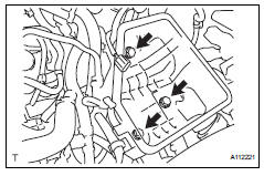
- Disconnect the mass air flow meter connector.
- Remove the 2 clamps of the engine wire.
- Remove the 4 bolts from the air cleaner case.
- Disconnect the air cleaner case from the no. 1 Air cleaner inlet.
- Remove transaxle control cable assembly
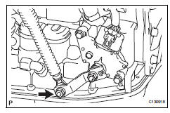
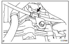
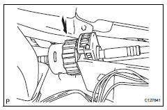
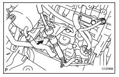
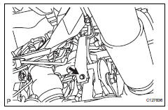
- Remove the nut and disconnect the control cable from the control shaft lever.
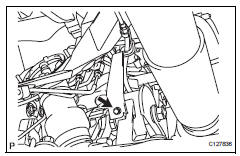
- Remove the clip and disconnect the control cable from the control cable bracket.
- Disconnect the control cable from the control cable support.
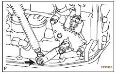
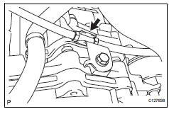
- Remove the bolt and disconnect the clamp of the control cable.
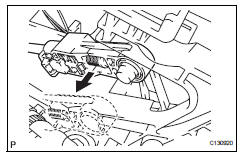
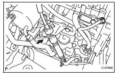
- Disconnect the control cable from the shift lever.
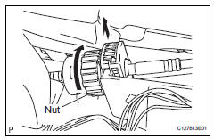
- Turn the nut and disconnect the control cable from the shift lever retainer.
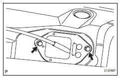
- Remove the 2 bolts and control cable.
- Install transaxle control cable assembly
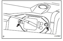
- Install the control cable with the 2 bolts.
Torque: 5.0 N*m (51 kgf*cm, 44 in.*Lbf)
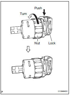
- Turn the nut of the control cable and push in the lock.
- Install the control cable onto the shift lever retainer.
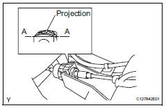
Notice:
- Install the cable with the protruding portion of the cable outer facing upward.
- After installing, check that the lock of the cable outer is protruding beyond portion a-a, as shown in the illustration.
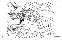
- Connect the control cable to the shift lever.
Notice:
Connect the control cable so that the adjusting mechanism lock of the control cable is installed on the driver side of the vehicle.
- Fix the control cable onto the control cable bracket with the clip.
- Connect the control cable onto the control shaft lever with the nut.
Torque: 12 n*m (122 kgf*cm, 9 ft.*Lbf)
- Connect the clamp of the control cable with the bolt.
Torque: 12 n*m (122 kgf*cm, 9 ft.*Lbf)
- Connect the control cable to the cable support.
- Install air cleaner assembly
- Connect the air cleaner case to the no. 1 Air cleaner inlet.
- Install the air cleaner case with the 4 bolts.
Torque: 5.0 N*m (51 kgf*cm, 44 in.*Lbf)
- Connect the 2 clamps of the engine wire.
- Connect the mass air flow meter connector.
- Install battery
- Install the battery bracket reinforcement with the 2
bolts.
Torque: 20 n*m (204 kgf*cm, 15 ft.*Lbf)
- Install the battery carrier with the 4 bolts.
Torque: 20 n*m (204 kgf*cm, 15 ft.*Lbf)
- Install the battery tray.
- Connect the 2 clamps of the engine wire.
- Install the battery with the battery clamp.
Torque: 8.5 N*m (87 kgf*cm, 75 in.*Lbf) for bolt
5.0 N*m (51 kgf*cm, 44 in.*Lbf) for nut
- Connect cable to negative battery terminal
- Inspect shift lever position
- When shifting the lever from p to the r position with the ignition switch on (ig) and the brake pedal depressed, make sure that the shift lever moves smoothly and moves correctly into position.
- Start the engine and make sure that the vehicle
moves forward when shifting the lever from n to the
d position and moves rearward when shifting the
lever to the r position.
If the operation cannot be performed as specified, inspect the park/neutral position switch and check the shift lever installation condition.
- Adjust shift lever position (see page ax-138)
- Install rear console box sub-assembly
- Install the rear console box (see page ip-26).
 Transmission oil cooler
Components
Removal
Remove transmission oil cooler
*1: Disconnect the no. 3 Water by-pass hose from
the transmission oil cooler.
*2: Disconnect the no. 4 Water by-pass hose from
...
 Floor shift assembly
Components
Removal
Disconnect cable from negative battery
terminal
Caution:
Wait at least 90 seconds after disconnecting the
cable from the negative (-) battery terminal to
preven ...
Other materials:
Removal
Disconnect cable from negative battery terminal
Caution:
Wait at least 90 seconds after disconnecting the
cable from the negative (-) battery terminal to
prevent airbag and seat belt pretensioner activation.
Remove mass air flow meter
Disconnect the mass air flow meter connector.
...
Front seatback heater
Inspection
Inspect front seatback heater assembly
lh
Measure the resistance of the seatback heater.
Standard resistance
If the result is not as specified, replace the seatback
heater assembly
Inspect front seatback heater assembly
rh
Hint:
Use the same procedures desc ...
Child restraint system
â– Types of child restraint system installation methods
Confirm with the operation manual enclosed with the child restraint
system about the installation of the child restraint system.
Seat belt attachment
Child restraint LATCH
anchors attachment
Anchor brackets (for
top tether strap) attachment
...
