Toyota RAV4 (XA40) 2013-2018 Service Manual: Underdrive planetary gear
Components
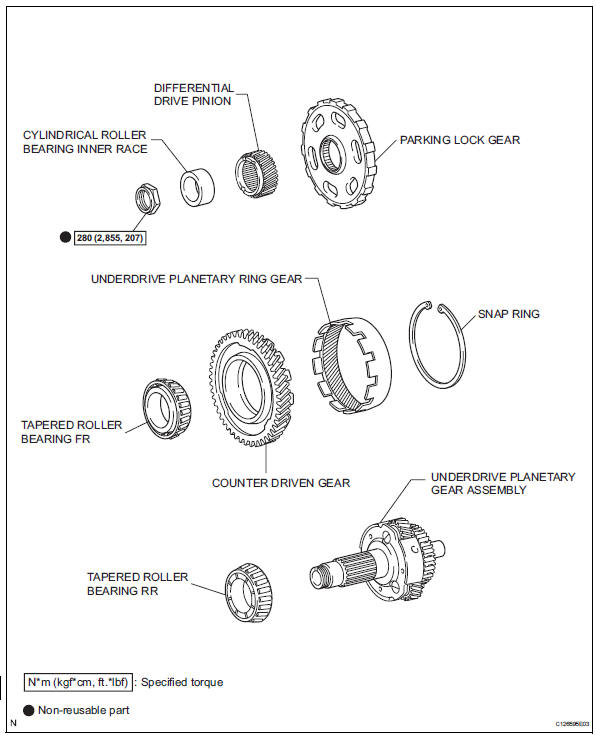
Disassembly
- Remove underdrive planetary gear preload (see page ax-240)
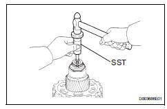
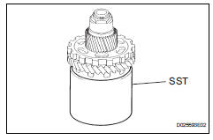
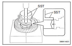
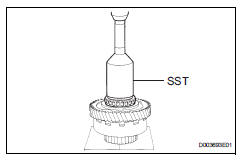
- Remove underdrive input shaft nut
Sst 09930-00010 (09931-00010, 09931-00020), 09387-00050, 09564-16020
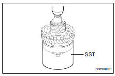
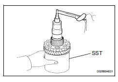
- Using sst, loosen the staked part of the nut.
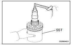
- Clamp the underdrive planetary gear in soft jaw vise.
Notice:
Be careful not to damage the differential drive pinion.
- Using sst, remove the lock nut.
Sst 09387-00050
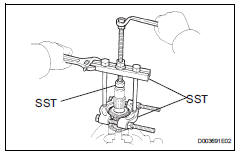
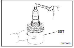
- Remove cylindrical roller bearing inner race
- Using sst, remove the cylindrical roller bearing race inner.
Sst 09950-00020, 09950-00030, 09950-60010 (09951-00340)
- Remove underdrive planetary gear assembly
- Using sst and a press, remove the differential drive pinion, parking lock gear, counter driven gear with underdrive planetary ring gear and front tapered roller bearing.
Sst 09387-00050
- clamp the underdrive planetary gear in soft jaw vise.
- Using sst, remove the rear tapped roller bearing from the underdrive planetary gear.
Sst 09950-00020, 09950-00030, 09950-60010 (09951-00340)
- Remove underdrive planetary ring gear
- Using snap ring pliers, remove the snap ring.
- Remove the underdrive planetary ring gear from the counter driven gear.
Inspection
- Inspect underdrive planetary gear preload
- Using sst, fix the underdrive planetary gear.
Sst 09387-00050
- Using sst and a torque wrench, measure the turning torque of the underdrive planetary gear in place while rotating the torque wrench at 60 rpm.
Sst 09387-00050
Torque: turning torque at 60 rpm
0.10 To 4.41 N*m (1.0 To 45 kgf*cm, 0.9 To 39 in.*Lbf)
Hint:
Use a torque wrench with a fulcrum length of 160 mm (6.3 In.)
Reassembly
- Install underdrive planetary ring gear
- Install a new snap ring to the outer race of the tapered roller bearing.
- Using a piston ring compressor, squeeze the snap ring.
- Using sst a press, press in the outer race of the tapered roller bearing.
Sst 09950-60020 (09951-00890), 09950-70010 (09951-07100)
- Install the underdrive planetary ring gear to the counter driven gear.
- Using snap ring pliers, install the snap ring.
- Install underdrive planetary gear assembly
- Using a press, press in the rear tapered roller bearing to the underdrive planetary gear.
Notice:
Press in the bearing until it becomes flat at the bottom
- Press in the bearing until it becomes flat at the bottom
- Using sst and a press, press in the front tapered roller bearing.
Sst 09214-76011
Notice:
Press in the counter driven gear while rotating it.
- Using a press, press in the parking lock gear.
Notice:
Press in the counter driven gear while rotating it.
- Install cylindrical roller bearing inner race
- Using a press, press in the cylindrical roller bearing race inner.
Notice:
Press in the counter driven gear while rotating it.
- Install underdrive input shaft nut
- Clamp the underdrive planetary gear in a soft jaw vise.
Notice:
Be careful not to damage the differential drive pinion.
- Using a socket wrench, install a new lock nut.
Torque: 280 n*m (2,855 kgf*cm, 207 in.*Lbf)
Hint:
Use a torque wrench with a fulcrum length of 750 mm (29.53 In.)
- Inspect underdrive planetary gear preload
- Using sst and a torque wrench, measure the turning torque of underdrive planetary gear assembly while rotating the torque wrench at 60 rpm.
Sst 09387-00050
Torque: turning torque at 60 rpm 0.10 To 4.41 N*m (1.0 To 45 kgf*cm, 0.9 To 39 in.*Lbf)
Hint:
Use a torque wrench with a fulcrum length of 160 mm (6.30 In.)
- Using a pin punch and a hammer, stake the lock nut.
Notice:
Make sure that there are no cracks on the nut.
 Direct clutch
Components
Disassembly
Inspect pack clearance of direct clutch
(see page ax-234)
Remove direct multiple disc clutch disc
Using a screwdriver, pry out the snap ring from the
direct ...
 Underdrive clutch
Components
Disassembly
Inspect pack clearance of underdrive
clutch (see page ax-247)
Remove no. 1 Underdrive clutch disc
Using a screwdriver, pry out the underdrive clutch
fla ...
Other materials:
Bluetooth®
When using the bluetooth® audio system
In the following conditions, the system may not function.
If the portable audio player is turned off
If the portable audio player is not connected
If the portable audio player’s battery is low
There may be a delay if a cellular phone connection i ...
All-wheel drive lock
switch (awd models)
All-wheel drive lock mode can be used when a large amount of
drive power needs to be applied to all the wheels, such as when
the vehicle gets stuck in mud and you need to free it.
Press the switch.
The torque of the engine is distributed
to the rear wheels to the maximum
extent possible in
ac ...
How to proceed with troubleshooting
Hint:
Use these procedures to troubleshoot the sliding roof
system.
*: Use the intelligent tester.
Vehicle brought to workshop
Inspect battery voltage
Standard voltage:
11 to 14 v
If the voltage is below 11 v, recharge or replace the battery
before proceeding.
Inspe ...
