Toyota RAV4 (XA40) 2013-2018 Service Manual: Air mix damper control servo motor circuit (passenger side)

Description
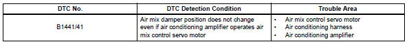
The air mix damper servo sends pulse signals to indicate the damper position to the air conditioning amplifier. The air conditioning amplifier activates the motor (normal or reverse) based on these signals to move the air mix damper (passenger seat) to the appropriate position. This adjusts the amount of air passing through the heater core after passing the evaporator and controls the temperature of the blown air
Hint:
Confirm that there are no mechanical problems because this dtc can be output when either a damper link or damper is mechanically locked.
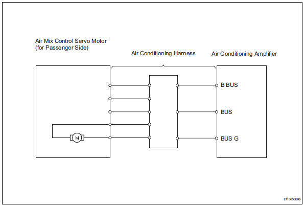
Wiring diagram
Inspection procedure
- Read value of intelligent tester (air mix pulse-p)
- Connect the intelligent tester (with can vim) to the dlc3.
- Turn the ignition switch on and turn the intelligent tester main switch on.
- Select the items below in the data list, and read the value displayed on the intelligent tester.
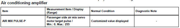
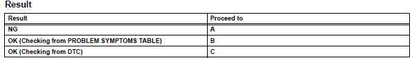
Ok: the display is as specified in the normal condition column.

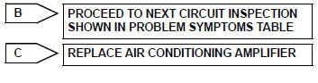
- Replace air mix control servo motor
Hint:
Since the servo motor cannot be tested when it is removed from the vehicle, replace the servo motor with a normal one and check that the condition returns to normal.
Ok: same problem does not occur.

System is ok
 Solar sensor circuit (driver side)
Description
The solar sensor, which is installed on the upper side of the instrument
panel, detects sunlight and
controls the air conditioning auto mode. The output voltage from the solar
se ...
 Air inlet damper control servo motor circuit
Description
The damper servo (air inlet control) sends pulse signals to indicate the
damper position to the air
conditioning amplifier. The air conditioning amplifier activates the motor
(no ...
Other materials:
Oxygen (a/f) sensor heater control circuit
Hint:
Although the dtc titles say oxygen sensor, these dtcs relate to the
air-fuel ratio (a/f) sensor.
Sensor 1 refers to the sensor mounted in front of the three-way
catalytic converter (twc) and
located near the engine assembly.
Description
Refer to dtc p2195 (see page es-292 ...
Propeller shaft assembly
Components
Removal
Remove propeller shaft with center bearing
shaft assembly
Remove the 2 bolts and 2 adjusting washers, and
disconnect the propeller with center bearing shaft.
Notice:
During the removal, do not exert excessive
force on the universal joint.
When r ...
Do-it-yourself service
precautions
If you perform maintenance by yourself, be sure to follow the
correct procedure as given in these sections.
Caution
The engine compartment contains many mechanisms and fluids that may
move suddenly, become hot, or become electrically energized. To avoid death
or serious injury, obse ...
