Toyota RAV4 (XA40) 2013-2018 Service Manual: Compressor lock sensor circuit
![]()
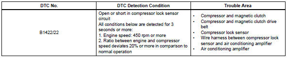
Description
This sensor sends 1 pulse per engine revolution to the air conditioning amplifier. If the ratio of the compressor speed divided by the engine speed is smaller than a predetermined value, the air conditioning amplifier turns the compressor off, and the indicator blinks at approximately 1 second intervals.
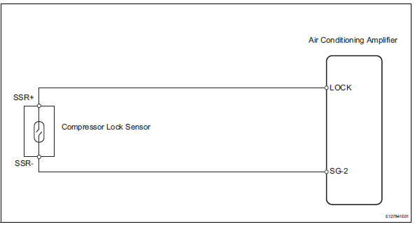
Wiring diagram
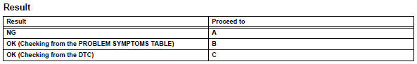
Inspection procedure
- Check air conditioning amplifier (lock signal)
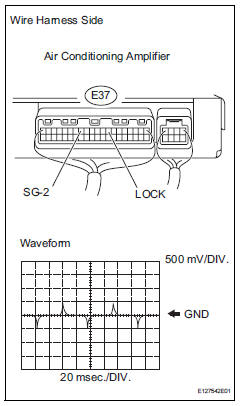
- Remove the air conditioning amplifier with its connectors still connected.
- Check the waveform of the amplifier connector.
Ok:
waveform is as shown in the illustration.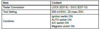

- Inspect compressor lock sensor
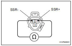
- Disconnect the b47 compressor lock sensor connector.
- Measure the resistance of the sensor.
Standard resistance

- Check wire harness (compressor lock sensor - air conditioning amplifier)
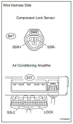
- Disconnect the b47 compressor lock sensor connector.
- Disconnect the e37 amplifier connector.
- Measure the resistance of the wire harness side connectors.
Standard resistance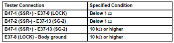

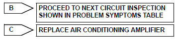
Replace air conditioning amplifier
 Solar sensor circuit (passenger side)
Description
The solar sensor, which is installed on the upper side of the instrument
panel, detects sunlight and
controls the air conditioning auto mode. The output voltage from the solar
se ...
 Pressure sensor circuit
Description
This dtc is output when the refrigerant pressure is either extremely low
(0.19 Mpa [2.0 Kgf/cm2, 28 psi]
or less) or extremely high (3.14 Mpa [32.0 Kgf/cm2, 455 psi] or more). The ...
Other materials:
Usb port/aux port
Connect an ipod, usb memory device or portable audio player
to the usb/aux port as indicated below. Select “ipod”, “usb” or
“aux” on the audio source selection screen and the device can
be operated via audio system.
Connecting using the usb/aux port
Ipod
Open the cover and connect ...
Diagnosis system
Description
Key reminder warning system data can be read
through the data link connector 3 (dlc3) of the
vehicle. When the system seems to be
malfunctioning, use the intelligent tester (with can
vim) to check for malfunctions and perform repairs.
Check dlc3
The vehi ...
Utility vehicle precautions
This vehicle belongs to the
utility vehicle class, which
has higher ground clearance
and narrower tread in
relation to the height of its
center of gravity to make it
capable of performing in a
wide variety of off-road
applications.
Utility vehicle feature
Specific design characteristics
give it a ...
