Toyota RAV4 (XA40) 2013-2018 Service Manual: Solar sensor circuit (passenger side)
![]()
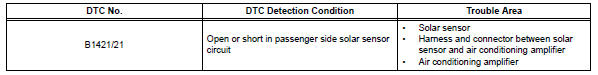
Description
The solar sensor, which is installed on the upper side of the instrument panel, detects sunlight and controls the air conditioning auto mode. The output voltage from the solar sensor varies in accordance with the amount of sunlight. When the sunlight increases, the output voltage increases. As the sunlight decreases, the output voltage decreases.
The air conditioning amplifier detects changes in the output voltage from the solar sensor.
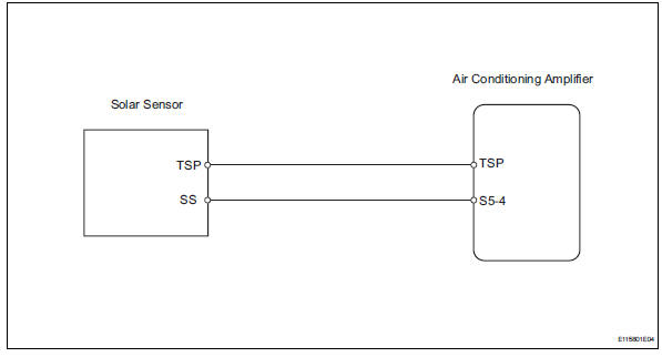
Wiring diagram
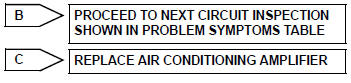
Inspection procedure
- Read value of intelligent tester (solar sens-p)
- Connect the intelligent tester (with can vim) to the dlc3.
- Turn the ignition switch on and turn the intelligent tester main switch on.
- Select the item below in the data list, and read the value displayed on the intelligent tester.
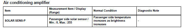
Ok: the display is as specified in the normal condition column.

- Inspect cooler (solar sensor) thermistor
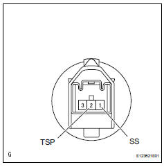
- Remove the solar sensor.
- Measure the resistance of the sensor.
- Connect the ohmmeter's positive (+) lead to terminal 1 and the negative (-) lead to terminal 2 of the solar sensor.
Standard resistance 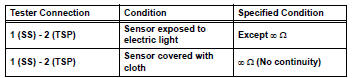
Notice:
The connection procedure for using a digital tester such as an electrical tester is shown above. When using an analog tester, connect the positive (+) lead to terminal 2 and the negative (-) lead to terminal 1 of the solar sensor.
Hint:
- As the inspection light is moved away from the sensor, the voltage decreases.
- Use an incandescent light for the inspection. Position it about 30 cm (11.8 In.) From the solar sensor.

- Check wire harness (solar sensor - air conditioning amplifier)
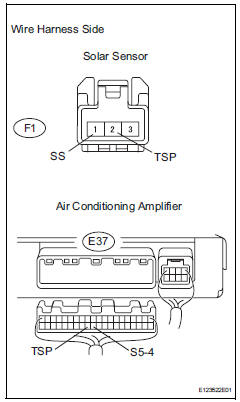
- Disconnect the f1 sensor connector.
- Disconnect the e37 amplifier connector.
- Measure the resistance of the wire harness side connectors.
Standard resistance 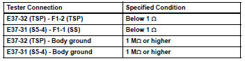

Replace air conditioning amplifier
 Evaporator temperature sensor circuit
Description
The no. 1 Cooler thermistor (evaporator temperature sensor) is installed on
the evaporator in the air
conditioning unit to detect the temperature of the cooled air that has passed ...
 Compressor lock sensor circuit
Description
This sensor sends 1 pulse per engine revolution to the air conditioning
amplifier. If the ratio of the
compressor speed divided by the engine speed is smaller than a predetermined ...
Other materials:
Fuel pressure regulator
Components
Removal
Remove fuel tank assembly
Remove the fuel tank (see page fu-39).
Remove fuel tank main tube sub-assembly
Remove the joint clip and fuel tank main tube.
Caution:
Before removing the tube joint clip, check for
foreign matter around the cli ...
Cooling fan relay
On-vehicle inspection
Disconnect cable from negative battery
terminal
Caution:
Wait at least 90 seconds after disconnecting the
cable from the negative (-) battery terminal to
prevent airbag and seat belt pretensioner activation.
Remove engine room no. 2 Relay block
cover
Inspect ...
Test mode procedure
Hint:
By switching the skid control ecu from normal mode to
test mode, abnormality detection sensitivity is enhanced
and troubleshooting can be conducted efficiently.
Perform a sensor check in test mode after the speed
sensor or sensor rotor has been repaired or replaced.
If the igniti ...
