Toyota RAV4 (XA40) 2013-2018 Service Manual: Diaphragm oil seal
Components
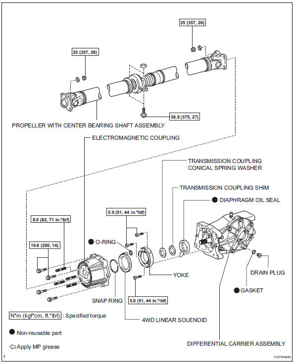
Removal
- Drain differential oil
- Using a 10 mm socket hexagon wrench, remove the rear differential drain plug and gasket, and drain the oil.
- Install a new gasket to the rear differential drain plug.
- Using a 10 mm socket hexagon wrench, install the rear differential drain plug and gasket.
- Remove propeller with center bearing shaft assembly (see page pr-3)
- Remove electromagnetic coupling (see page df-21)
- Remove 4wd linear solenoid (see page df-22)
- Remove yoke (see page df-22)
- Remove transmission coupling conical spring washer (see page df-22)
- Remove transmission coupling shim (see page df-22)
- Remove diaphragm oil seal
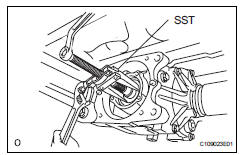
- Using sst, remove the oil seal from the rear differential carrier.
Sst 09308-10010
Installation
- Install diaphragm oil seal
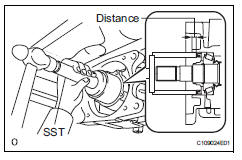
- Apply a light coat of mp grease no. 2 To the lip of a new diaphragm oil seal.
- Using sst and a hammer, tap the diaphragm oil seal into the rear differential carrier according to the specification.
Sst 09710-30021 (09710-03121), 09950-60010 (09951-00570), 09950-70010 (09951-07100)
Standard distance: 7.0 +-0.5 Mm (0.28 +-0.02 In.)
- Install transmission coupling shim (see page df-41)
- Install transmission coupling conical spring washer (see page df-41)
- Install yoke (see page df-41)
- Install 4wd linear solenoid (see page df-41)
- Install electromagnetic coupling (see page df-42)
- Temporarily install propeller with center bearing shaft assembly (see page pr-5)
- Fully tighten propeller with center bearing shaft assembly (see page pr-6)
- Inspect and adjust joint angle (see page pr- 4)
- Add differential oil
- Add differential oil (see page df-3).
- Check for differential oil leakage
If gas is leaking, tighten the areas necessary to stop the leak. Replace damaged parts as necessary.
 Rear differential side gear shaft oil seal
Components
Removal
Drain differential oil (see page df-10)
Remove tailpipe assembly
Remove the tailpipe (see page ex-2).
Remove center exhaust assembly
Remove propelle ...
 Rear differential carrier assembly
Components
...
Other materials:
Wireless charger (if
equipped)
A portable device can be
charged by just placing Qi standard
wireless charge compatible
portable devices according to
the Wireless Power Consortium,
such as smartphones and
mobile batteries, etc., on the
charge area.
This function cannot be used
with portable devices that are
larger than the chargi ...
On-vehicle inspection
Check driver side seat belt warning light
Turn the ignition switch on.
When the driver side seat belt is not fastened, check
that the combination meter's driver side seat belt
warning light starts blinking.
When the seat belt is fastened, check that the
combination meter's driver ...
Receiver error
Description
Wiring diagram
Inspection procedure
Notice:
It is necessary to register an id code after replacing the tire pressure
warning valve abd
transmitter and/or the tire pressure warning ecu (see page tw-9).
Hint:
Set the tire pressure to the specified value.
Standard pres ...
