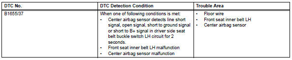
Toyota RAV4 (XA40) 2013-2018 Service Manual: Driver side seat belt buckle switch circuit malfunction

Description
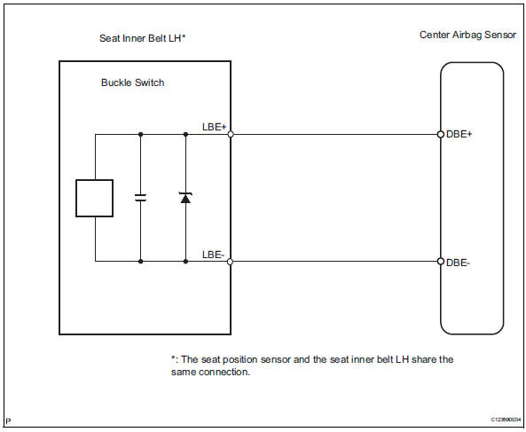
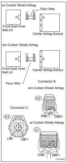
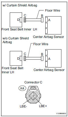
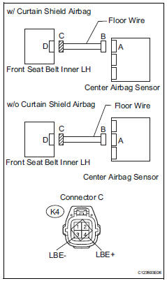
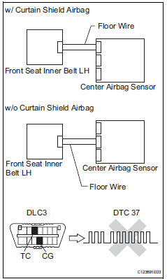
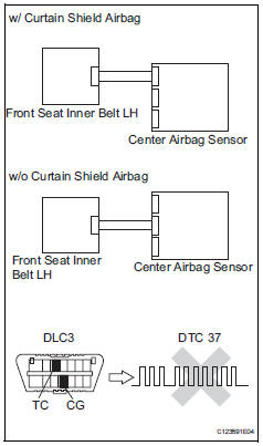
The driver side seat belt buckle switch circuit consists of the center airbag sensor and the front seat inner belt lh.
Dtc b1655/37 is recorded when a malfunction is detected in the driver side seat belt buckle switch circuit.
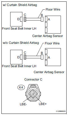
Wiring diagram
Inspection procedure
- Check for dtc
- Turn the ignition switch on, and wait for at least 60 seconds.
- Clear the dtcs (see page rs-49).
- Turn the ignition switch off.
- Turn the ignition switch on, and wait for at least 60 seconds.
- Check the dtcs (see page rs-49).
Ok: dtc b1655/37 is not output.
Hint
Dtcs other than dtc b1655/37 may be output at this time, but they are not related to this check.


- Check connection of connector
- Turn the ignition switch off.
- Disconnect the cable from the negative (-) battery terminal, and wait for at least 90 seconds.
- Check that the connectors are properly connected to the center airbag sensor and the front seat inner belt lh.
Ok: the connectors are properly connected.

- Check floor wire (open)
- Disconnect the connectors from the center airbag sensor and the front seat inner belt lh.
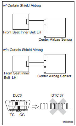
- Using a service wire, connect k2-11 (lbe+) and k2-12 (lbe-) (w/o curtain shield airbag), or k1-10 (dbe+) and k1-18 (dbe-) (w/curtain shield airbag) of connector b.
Notice:
Do not forcibly insert the service wire into the terminals of the connector when connecting.
- Measure the resistance of the wire harness side connector.
Standard resistance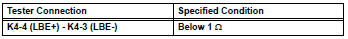

- Check floor wire (short)
- Disconnect the service wire from connector b.
- Measure the resistance of the wire harness side connectors.
Standard resistance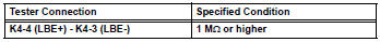


- Check floor wire (to b+)
- Connect the cable to the negative (-) battery terminal, and wait for at least 2 seconds.
- Turn the ignition switch on.
- Measure the voltage of the wire harness side connector.
Standard voltage 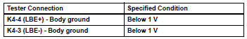

- Check floor wire (to ground)
- Turn the ignition switch off.
- Disconnect the cable from the negative (-) battery terminal, and wait for at least 90 seconds.
- Measure the resistance of the wire harness side connectors.
Standard resistance 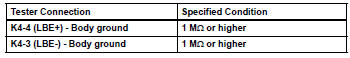

- Check front seat inner belt assembly lh
- Connect the connector to the center airbag sensor and the front seat inner belt lh.
- Connect the negative (-) terminal cable to the battery, and wait for at least 2 seconds.
- Turn the ignition switch on, and wait for at least 60 seconds.
- Clear the dtcs (see page rs-49).
- Turn the ignition switch off.
- Turn the ignition switch on, and wait for at least 60 seconds.
- Check the dtcs (see page rs-49).
Ok: dtc b1655/37 is not output.
Hint:
Dtcs other than dtc b1655/37 may be output at this time, but they are not related to this check.


- Replace front seat inner belt assembly lh
- Turn the ignition switch off.
- Disconnect the cable from the negative (-) battery terminal, and wait for at least 90 seconds.
- Replace the front seat inner belt lh (see page sb-21).
Hint:
Perform the inspection using parts from a normal vehicle if possible.

- Check center airbag sensor assembly
- Connect the cable to the negative (-) battery terminal, and wait for at least 2 seconds.
- Turn the ignition switch on, and wait for at least 60 seconds.
- Clear the dtcs (see page rs-49).
- Turn the ignition switch off.
- Turn the ignition switch on, and wait for at least 60 seconds.
- Check the dtcs (see page rs-49).
Ok: dtc b1655/37 is not output.
Hint:
Dtcs other than dtc b1655/37 may be output at this time, but they are not related to this check.

End
 Seat position airbag sensor circuit malfunction
Description
The seat position sensor circuit consists of the center airbag sensor and the
seat position sensor.
Dtc b1653/35 is recorded when a malfunction is detected in the seat position
...
 Passenger airbag on / off indicator circuit malfunction
Description
The passenger airbag on / off indicator circuit consists of the center airbag
sensor and the heater
control panel*1 or *2.
This circuit indicates the operation condition of the ...
Other materials:
Engine immobilizer system
The vehicle's keys have
built-in transponder chips
that prevent the engine from
starting if a key has not
been previously registered
in the vehicle's on-board
computer.
Never leave the keys inside
the vehicle when you leave
the vehicle.
This system is designed to
help prevent vehicle theft but
does ...
PCS (Pre-Collision System)
The pre-collision system
uses a radar sensor and
front camera to detect
objects in front of
the vehicle. When the system
determines that the
possibility of a frontal collision
with an object is high,
a warning operates to urge
the driver to take evasive
action and the potential
brake pressure is inc ...
Before driving
Floor mat
Use only floor mats designed specifically for vehicles of the same
model and model year as your vehicle. Fix them securely in place
onto the carpet.
Insert the retaining hooks (clips)
into the floor mat eyelets.
Turn the upper knob of each
retaining hook (clip) to secure
t ...
