Toyota RAV4 (XA40) 2013-2018 Service Manual: Disassembly
- Remove radio setting condenser

- Remove the bolt and condenser.
- Remove oil pressure switch
- Using a 24 mm deep socket wrench, remove the sensor.
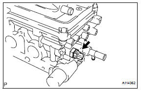
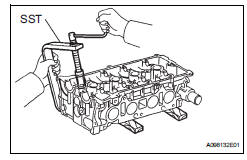
- Remove engine coolant temperature sensor
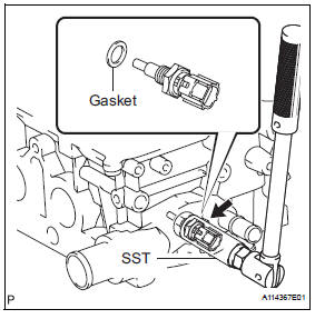
- Using sst, remove the sensor and gasket.
Sst 09817-33190
- Remove camshaft position sensor
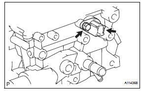
- remove the bolt and sensor.
- Remove no. 2 Camshaft bearing
- Remove the no. 2 Camshaft bearing.
- Remove no. 1 Camshaft bearing
- Remove the no. 1 Camshaft bearing.
- Remove valve lifter
Hint:
Arrange the valve lifters in the correct order.
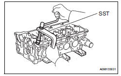
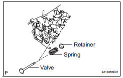
- Remove intake valve
- Place the cylinder head on wooden blocks.
- Using sst, compress the spring, then remove the 2 retainer locks.
Sst 09202-70020 (09202-00010)
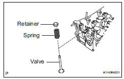
- Remove the retainer, spring and valve from the cylinder head.
Hint:
Arrange the removed parts in the correct order.
- Remove exhaust valve
- Place the cylinder head on wooden blocks.
- Using sst, compress the spring, then remove the 2 retainer locks.
Sst 09202-70020 (09202-00010)
- Remove valve spring seat
- Using compressed air and a magnetic finger, remove the spring seat by blowing air.
Hint:
Arrange the valves, valve springs, spring seats and spring retainers in the correct order.
- Remove valve stem oil seal
- Using needle-nose pliers, remove the 16 oil seals.
 Removal
Discharge fuel system pressure (see page
fu-9)
Disconnect cable from negative battery
terminal
Caution:
Wait at least 90 seconds after disconnecting the
cable from the negative (-) batte ...
 Inspection
Inspect cylinder head for warpage
Using a precision straightedge and feeler gauge,
measure the warpage of the contact surfaces of the
cylinder block and manifolds.
Maximum warpage: ...
Other materials:
Reassembly
Hint:
When installing the ornament plate and emblem, heat the
radiator grille, ornament plate and emblem using a heat light.
Standard heating temperature
Notice:
Do not heat the emblem base and emblem excessively.
Install radiator grille emblem
Attach the 4 claws to install the radi ...
Open in stop light switch circuit
Description
The skid control ecu detects the brake operating conditions through a signal
transmitted by the stop light
switch. The skid control ecu incorporates an open circuit detection circuit.
This dtc is set under either of
the following conditions:
An open is detected in the stop lig ...
