Toyota RAV4 (XA40) 2013-2018 Service Manual: Dtc check / clear
- Check dtc
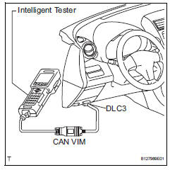
- When using intelligent tester:
- Connect the intelligent tester (with can vim) to the dlc3.
- Turn the ignition switch on and press the intelligent tester main switch on.
- Read the dtcs by following the prompts on the intelligent tester.
Hint:
Refer to the intelligent tester operator's manual for further details.
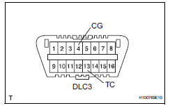
- When not using intelligent tester:
- Using sst, connect terminals 13 (tc) and 4
(cg) of the dlc3.
Sst 09843-18040
- Turn the ignition switch on.
- Read and write down any dtcs indicated by the
p/s warning light on the combination meter.
Refer to the chart below for examples of a normal code and dtcs 21 and 22.
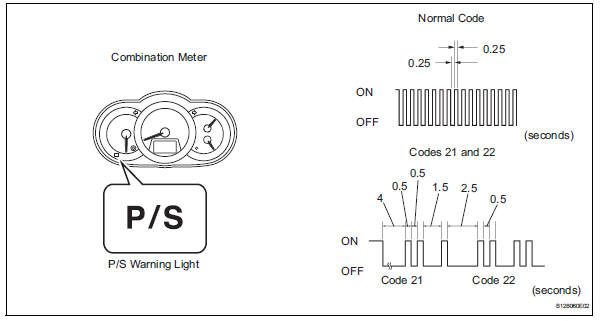
Hint:
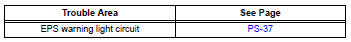
- If the p/s warning light does not blink to
display any dtcs set or the normal code,
inspect the circuit shown in the table below.
- If two or more malfunctions are detected simultaneously, dtcs will be displayed in ascending numerical order.
- Refer to the diagnostic trouble code chart (see page ps-16) for dtc information.
- Clear dtc
- When using intelligent tester:
- Connect the intelligent tester (with can vim) to the dlc3.
- Turn the ignition switch on and press the intelligent tester main switch on.
- Clear the dtcs by following the prompts on the intelligent tester.
- Turn the ignition switch off.
- Disconnect the intelligent tester from the dlc3.
- When not using intelligent tester:
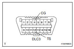
- Using sst, connect terminals 12 (ts) and 4
(cg) of the dlc3.
Sst 09843-18040
- Turn the ignition switch on.
- Disconnect the sst check wire from terminal 4 (cg) and reconnect it, and repeat this procedure 4 times or more within 8 seconds.
- Check that the p/s warning light blinking pattern is the normal code.
- Turn the ignition switch off.
- Remove sst from the dlc3.
 Diagnosis system
Check dlc3
Check the dlc3:
the power steering ecu uses can (iso11898-1)
and iso9141-2 for communication protocol. The
terminal arrangement of the dlc3 complies with
sae j1962 and ...
 Freeze frame data
Freeze frame data
Notice:
It is difficult to show the specified values
(judgment values) clearly because freeze frame
data values change significantly due to
differences in measurement ...
Other materials:
Problem symptoms table
Hint:
Use the table below to help determine the cause of the
problem symptom. The potential causes of the symptoms
are listed in order of probability in the "suspected area"
column of the table. Check each symptom by checking the
suspected areas in the order they are listed. Re ...
Front door courtesy switch
Components
Removal
Hint:
Use the same procedures for the rh and lh sides.
The procedures listed below are for the lh side.
Disconnect cable from negative battery
terminal
Caution:
Wait at least 90 seconds after disconnecting the
cable from the negative (-) battery terminal t ...
Inspection
Inspect crankshaft position sensor
Measure the resistance of the sensor.
Standard resistance
Notice:
Cold and hot mean the temperature of the coils
themselves. Cold is from -10 to 50°c (14 to
122°f) and hot is from 50 to 100°c (122 to
212°f).
If the result is not as specif ...
