
Toyota RAV4 (XA40) 2013-2018 Service Manual: Ecm communication stop mode (2005/11-2006/01)
Description

Wiring diagram
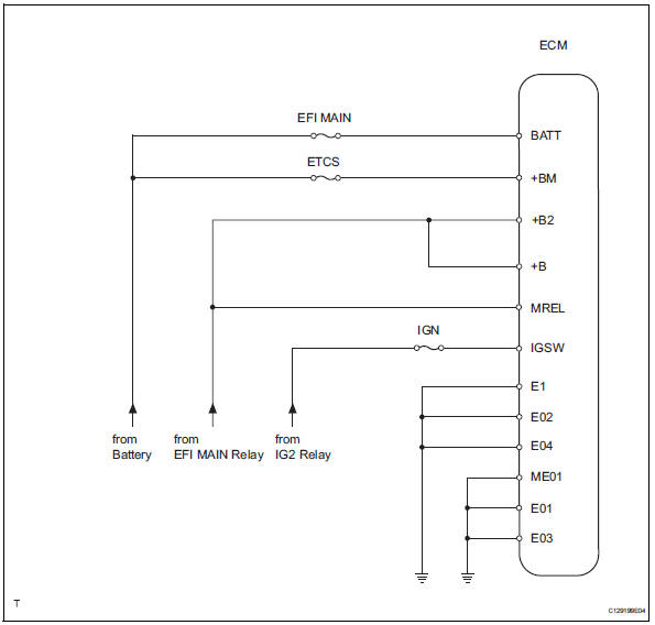
Inspection procedure
Notice:
- Turn the ignition switch off before measuring the resistances of the main wire and the branch wire.
- After the ignition switch is turned off, check that the key reminder warning system and light reminder warning system are not in operation.
- Before measuring the resistance, leave the vehicle for at least 1 minute and do not operate the ignition switch, any switches or doors. If doors need to be opened in order to check connectors, open the doors and leave them open.
Hint:
Operating the ignition switch, any switches or any doors triggers related ecu and sensor communication with the can, which causes resistance variation.
- Check wire harness (ecm - battery and body ground)

- Disconnect the a9 and b30 ecm connectors.
- Measure the resistance of the wire harness side connector.
Standard resistance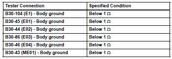
- Measure the voltage of the wire harness side connector.
Standard voltage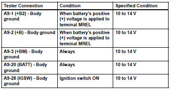


Replace ecm
 Yaw rate sensor communication stop mode
Description
Wiring diagram
Inspection procedure
Notice:
Turn the ignition switch off before measuring the resistances of the
main wire and the branch
wire.
After the ignition swi ...
 Ecm communication stop mode (2006/01- )
Description
Wiring diagram
Inspection procedure
Notice:
Turn the ignition switch off before measuring the resistances of the
main wire and branch
wire.
After the ignition swi ...
Other materials:
Short in front driver side - side squib circuit
Description
The driver side - side squib circuit consists of the center airbag sensor and
the front seat side airbag lh.
This circuit instructs the srs to deploy when the deployment conditions are met.
These dtcs are recorded when a malfunction is detected in the driver side - side
sq ...
Before driving
Floor mat
Use only floor mats designed specifically for vehicles of the same
model and model year as your vehicle. Fix them securely in place
onto the carpet.
Insert the retaining hooks (clips)
into the floor mat eyelets.
Turn the upper knob of each
retaining hook (clip) to secure
t ...
Dynamic radar cruise control
with full-speed range
In vehicle-to-vehicle distance
control mode, the
vehicle automatically accelerates,
decelerates and
stops to match the speed
changes of the preceding
vehicle even if the accelerator
pedal is not depressed.
In constant speed control
mode, the vehicle runs at a
fixed speed.
Use the dynamic radar
cru ...
