
Toyota RAV4 (XA40) 2013-2018 Service Manual: Front door belt moulding
Components
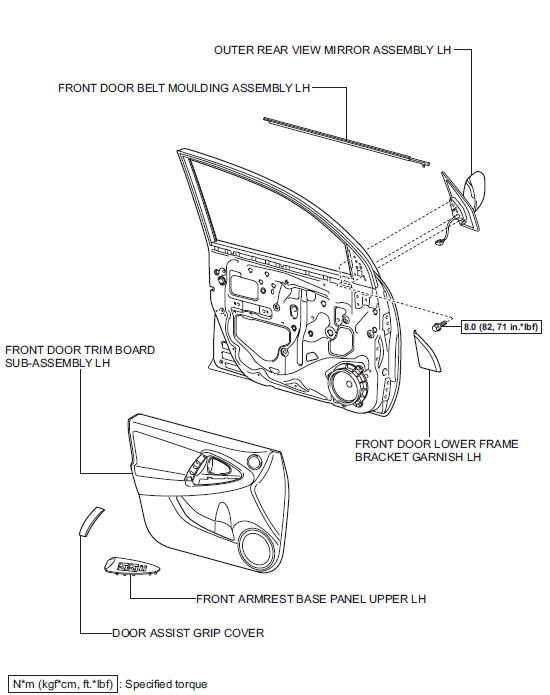
 Installation
Replace roof carrier seal
Remove the seals.
Install new seals as shown in the illustration.
Install roof rack leg front lh
Install the leg cushion front.
Install the roof ...
 Removal
Hint:
Use the same procedures for the rh side and lh side.
The procedures listed below are for the lh side.
Disconnect cable from negative battery terminal
Notice:
Wait at least 90 sec ...
Other materials:
Components (2005/11-2006/01)
Sliding roof ecu power source circuit
Description
If the sliding function and tilt function do not operate, there may be a
malfunction in the sliding roof ecu
power source circuit.
Wiring diagram
Inspection procedure
Perform active test by i ...
Using the cd player
Power
Volume
Cd eject
Selecting a track or displaying
track list
Searching playback
Random play or back button
Repeat play
Fast-forwarding or rewinding
Changing the audio source/
playback
Playback/pause
Selecting a track
Displaying text message
Loading cds
Insert ...
Evaporative emission leak detection pump
Dtc summary
Hint:
The leak detection pump is built into the canister pump module.
Description
The description can be found in the evap (evaporative emission) system (see
page es-335).
Inspection procedure
Refer to the evap system (see page es-340).
Monitor description
5 Hours* afte ...
