Toyota RAV4 (XA40) 2013-2018 Service Manual: Installation
- Install no. 2 Chain sub-assembly
- Set the crankshaft key in the left horizontal position.
- Turn the cutout of the drive shaft so that it faces upward.
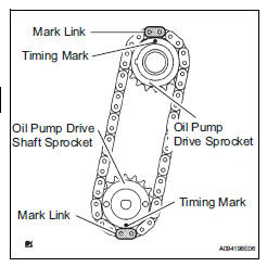
- Align the yellow mark links with the timing marks of each gear as shown in the illustration.
- Install the sprockets onto the crankshaft and oil pump shaft with the chain wrapped on the gears.
- Temporarily tighten the oil pump drive shaft sprocket with the nut.
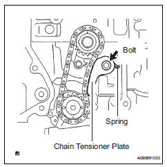
- Insert the damper spring into the adjusting hole, and
then install the chain tensioner plate with the bolt.
Torque: 12 n*m (122 kgf*cm, 9 ft.*Lbf)
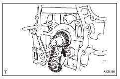
- Align the adjusting hole of the oil pump drive shaft sprocket with the groove of the oil pump.
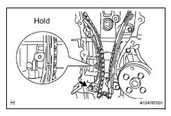
- Insert a 4 mm diameter bar into the adjusting hole of
the oil pump drive shaft gear to lock the gear in
position, and then tighten the nut.
Torque: 29.5 N*m (301 kgf*cm, 22 ft.*Lbf)
- Install crankshaft timing sprocket
- Install no. 1 Chain vibration damper
- Install the chain vibration damper with the 2 bolts.
Torque: 9.0 N*m (92 kgf*cm, 80 in.*Lbf)
- Install chain sub-assembly
- Set the no. 1 Cylinder to tdc/compression.
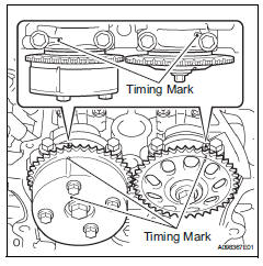
- Turn the camshafts with a wrench (using the hexagonal lobe) to align the timing marks of the camshaft timing gear with each timing mark located on the no. 1 And no. 2 Bearing caps as shown in the illustration.
- Using the crankshaft pulley bolt, turn the crankshaft to position the key on the crankshaft upward.
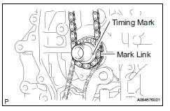
- Install the chain onto the crankshaft timing sprocket with the gold or orange mark link aligned with the timing mark on the crankshaft.
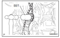
- Using sst and a hammer, tap in the crankshaft
timing sprocket.
Sst 09309-37010
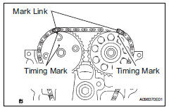
- Align the gold or yellow links with each timing mark located on the camshaft timing gear and sprocket, then install the chain.
- Install chain tensioner slipper
- Install the chain tensioner slipper with the bolt.
Torque: 19 n*m (194 kgf*cm, 14 ft.*Lbf)
- Install timing chain guide
- Install the timing chain guide with the bolt.
Torque: 9.0 N*m (92 kgf*cm, 80 in.*Lbf)
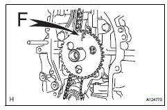
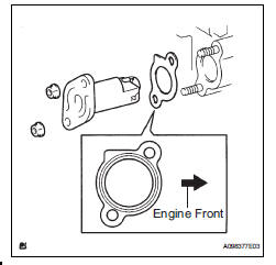
- Install no. 1 Crankshaft position sensor plate
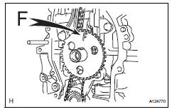
- Install the sensor plate with the "f" mark facing forward.
- Install timing chain cover sub-assembly
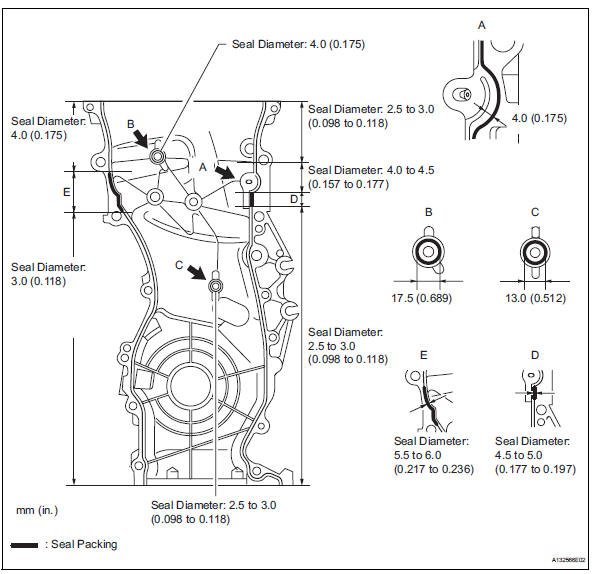
- Remove any old packing material and be careful not to drop any oil on the contact surfaces of the timing chain cover, cylinder head and cylinder block.
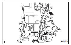
- Apply seal packing (diameter 4.0 To 4.5 Mm (0.157 To 0.177 In.)) As shown in the illustration.
Seal packing:
Toyota genuine seal packing block, three bond 1207b or equivalent
Notice:
- Remove any oil from the contact surface.
- Install the chain cover within 3 minutes of applying seal packing.
- Do not add engine oil for at least 2 hours after installing the chain cover.
- Apply a continuous bead of seal packing as shown in the illustration.
Seal packing:
Toyota genuine seal packing block, three bond 1207b or equivalent
Notice:
- Remove any oil from the contact surface.
- Install the chain cover within 3 minutes of applying seal packing.
- Do not add engine oil for at least 2 hours after installing the chain cover.
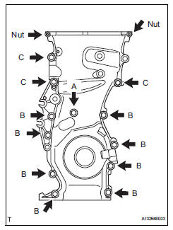
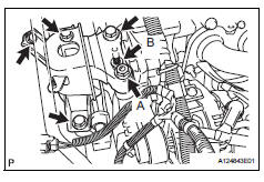
- Install the timing chain cover with the 12 bolts and 2 nuts.
Torque: 9.0 N*m (92 kgf*cm, 80 in.*Lbf) for bolt a
25 N*m (255 kgf*cm, 18 ft.*Lbf) for bolt b
55 N*m (561 kgf*cm, 41 ft.*Lbf) for bolt c
11 N*m (112 kgf*cm, 8 ft.*Lbf) for nut
Hint:
Bolt length: 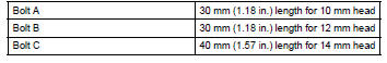
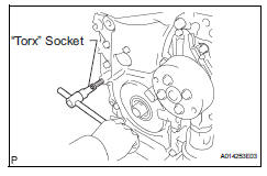
- Using an e10 "torx" socket, install the stud bolt for the v-ribbed belt tensioner
Torque: 21.5 N*m (219 kgf*cm, 16 ft.*Lbf)
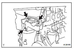
- Install no. 1 Chain tensioner assembly
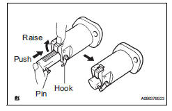
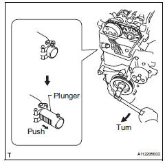
- Release the ratchet pawl, then fully push in the plunger and hook the hook to the pin so that the plunger is in the position shown in the illustration.
- Install a new gasket and the chain tensioner with the 2 nuts.
Torque: 9.0 N*m (92 kgf*cm, 80 in.*Lbf)
Notice:
When installing the chain tensioner, set the hook again if the hook releases the plunger.
- Install v-ribbed belt tensioner assembly
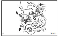
- Install the v-ribbed belt tensioner with the bolt and nut.
Torque: 59.5 N*m (607 kgf*cm, 44 ft.*Lb
f)
Notice:
Do not lift the engine more than necessary.
- Install engine mounting bracket rh
- Install the engine mounting bracket rh with the 3 bolts.
Torque: 55 n*m (561 kgf*cm, 41 ft.*Lbf)
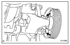
- Install crankshaft pulley
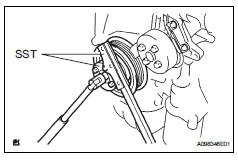
- Using sst, fix the pulley in place and tighten the bolt.
Sst 09213-54015 (91651-60855), 09330-00021 torque: 180 n*m (1,835 kgf*cm, 133 ft.*Lbf)
- Turn the crankshaft counterclockwise, then disconnect the plunger knock pin from the hook.
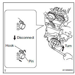
- Turn the crankshaft clockwise, then check that the plunger is extended.
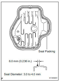
- Remove any old packing material and be careful not to drop any oil on the contact surfaces of the cylinder block and oil pan.
- Apply a continuous bead of seal packing (diameter 3.0 To 4.0 Mm (0.118 To 0.157 In.)) As shown in the illustration.
Seal packing: toyota genuine seal packing block, three bond 1207b or equivalent
Notice:
- Remove any oil from the contact surface.
- Install the oil pan within 3 minutes of applying seal packing.
- Do not add engine oil for at least 2 hours after installing the oil pan.
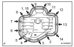
- install the oil pan to the cylinder block.
- Uniformly tighten the 12 bolts and 2 nuts in the sequence shown in the illustration.
Torque: 9.0 N*m (92 kgf*cm, 80 in.*Lbf)
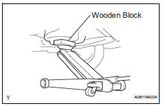
- Place a transmission jack underneath the engine, then put a wooden block on the jack.
- Remove the chain block and sling device.
- Remove the no. 1 And no. 2 Engine hangers.
- Install crankshaft position sensor (see page es-402)
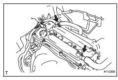
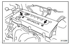
- Install cylinder head cover sub-assembly
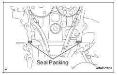
- Remove any old packing material from the contact surface.
- Apply seal packing to the 2 locations shown in the illustration.
Seal packing: toyota genuine seal packing block, three
Bond 1207b or equivalent
Notice:
- Remove any oil from the contact surface.
- Install the oil pan within 3 minutes of applying seal packing.
- Do not add engine oil for at least 2 hours after installing the oil pan.
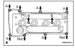
- Install the cylinder head cover with the 8 bolts and 2 nuts.
Torque: 11 n*m (112 kgf*cm, 8 ft.*Lbf) for bolt a
14 N*m (143 kgf*cm, 10 ft.*Lbf) for bolt b
11 N*m (112 kgf*cm, 8 ft.*Lbf) for nut
- Install the 2 engine wires with the 2 bolts.
Torque: 8.4 N*m (86 kgf*cm, 74 in.*Lbf)
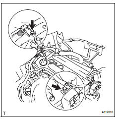
- Connect the 2 ventilation hoses to the cylinder head cover.
- Install spark plug (see page em-16)
- Install ignition coil assembly (see page ig-9)
- Install idler pulley
- Install the idler pulley with the 2 bolts.
Torque: 60 n*m (612 kgf*cm, 44 ft.*Lbf)
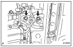
- Install engine mounting insulator rh
- Install the engine mounting insulator rh with the 4 bolts and 2 nuts.
Torque: 95 n*m (969 kgf*cm, 70 ft.*Lbf) for bo
95 N*m (969 kgf*cm, 70 ft.*Lbf) for nut a
52 N*m (530 kgf*cm, 38 ft.*Lbf) for nut b
- Connect the 2 clamps of the engine wire.
- Install the wire harness protector with the bolt.
- Install engine mounting insulator fr
- Install the engine mounting insulator fr with the 2 bolts.
Torque: 95 n*m (969 kgf*cm, 70 ft.*Lbf)
- Install the through bolt and nut.
Torque: 145 n*m (1,479 kgf*cm, 107 ft.*Lbf)
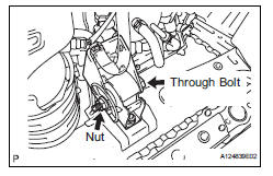
Hint:
Install the bolt which is used to secure the front engine mounting bracket fr.
- Install radiator reservoir
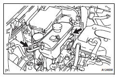
- Install the radiator reservoir with the 2 bolts.
Torque: 5.0 N*m (51 kgf*cm, 44 in.*Lbf)
- Install generator assembly (see page ch-15)
- Install fan and generator v belt (see page em-7)
- Install front suspension member reinforcement rh (see page em-7)
- Install front exhaust pipe (see page ex-4)
- Add engine oil (see page lu-4)
- Connect cable to negative battery terminal
- Check for engine oil leaks
- Check for exhaust gas leaks
- Install no. 1 Engine cover
- Install the engine cover with the 2 nuts.
Torque: 7.0 N*m (71 kgf*cm, 62 in.*Lbf)
- Install front fender apron rh
- Install no. 1 Engine under cover
- Install front wheel rh
- Install radiator support opening cover
 Replacement
Replace timing chain cover oil seal
Using a screwdriver and hammer, tap out the oil
seal.
Place the oil seal retainer on wooden blocks.
Apply multi-purpose grease to the lip of a ne ...
 Cylinder head
...
Other materials:
Automatic transaxle unit
Components
...
Check for intermittent problems
Check for intermittent problems
Hint:
A momentary interruption (open circuit) in the connectors
and/or wire harness between the sensors and ecus can
be detected by using the ecu data list function of an
intelligent tester.
Turn the ignition switch off and connect the
intelligent test ...
Installation
Hint:
Use the same procedures for the rh side and lh side.
The procedures listed below are for the lh side.
When installing the moulding, heat the vehicle body and
moulding using a heat light.
Standard heating temperature
Notice:
Do not heat the vehicle body and moulding
excessively ...
