Toyota RAV4 (XA40) 2013-2018 Service Manual: Installation
- Install rear differential support
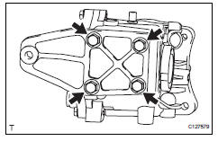
- Install the differential support to the differential carrier with the 4 bolts.
Torque: 98 n*m (999 kgf*cm, 72 ft.*Lbf)
- Install rear differential no. 1 And no. 2 Support
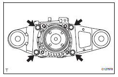
- Install the differential no. 1 And no. 2 Supports with
the 4 bolts to the differential carrier.
Torque: 55 n*m (561 kgf*cm, 41 ft.*Lbf)
- Install rear differential carrier subassembly
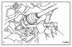
- Support the rear differential carrier with a transmission jack or equivalent
- Apply hypoid gear oil to the splines of the left and right rear drive shaft inboard joints.
- Align the splines of the rear drive shaft inboard joints and, using a brass bar and hammer, tap in the left and right rear drive shafts.
Notice:
- Face the cutout section of the snap ring downward.
- Do not damage the oil seal during the insertion.
- Do not strike the tip of the outboard joint with the hammer.
Hint:
Determine whether or not the rear drive shaft is completely tapped in by checking for changes in sound or the reaction force of the brass bar.
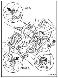
- Slowly raise the transmission jack, fix the nuts in place and install the 3 bolts.
Torque: 86 n*m (877 kgf*cm, 63 ft.*Lbf) for bolt a 140 n*m (1,428 kgf*cm, 103 ft.*Lbf) for bolt b
Notice:
Tighten the bolts, not the nuts.
- Connect the connector.
- Install the breather tube.
- Connect the harness clamp.
- Install rear suspension member brace lh
- Install the member brace to the suspension member with the 2 bolts.
Torque: 60 n*m (612 kgf*cm, 44 ft.*Lbf)
- Install rear suspension member brace rh
Hint:
Use the same procedures described for the lh side.
- Temporarily install propeller with center bearing shaft assembly (see page pr-5)
- Tighten propeller with center bearing shaft assembly (see page pr-6)
- Inspect joint angle (see page pr-4)
- Install center exhaust pipe assembly (see page ex-5)
- Install tailpipe assembly (see page ex-6)
- Install rear wheel torque: 103 n*m (1,050 kgf*cm, 76 ft.*Lbf)
- Add differential oil
- Add differential oil (see page df-3).
- Check for differential oil leakage
- Check for exhaust gas leakage
If gas is leaking, tighten the areas necessary to stop the leak. Replace damaged parts as necessary.
 Reassembly
Install wiring harness clamp bracket
Install the bracket with the bolt.
Install elbow tube
Install straight pin
Using a plastic hammer, install the 4 straight pins to
the ...
 Door lock
...
Other materials:
Rear brake flexible hose
Installation
Hint:
Use the same procedures for the lh side and rh side.
The procedures listed below are for the lh side.
Install rear brake tube flexible hose
Notice:
The gasket and union bolt must be used as a set, as
shown in the illustration.
Connect the flexible hose wi ...
RCTA (Rear Cross Traffic
Alert) function
The RCTA function uses the
BSM rear side radar sensors
installed behind the rear
bumper. This function is
intended to assist the driver
in checking areas that are
not easily visible when
backing up.
WARNING
â– Cautions regarding the use of
the system
The driver is solely responsible for
safe driving ...
Front wiper rubber
Components
Removal
Remove front wiper blade
Detach the claw as shown in the illustration.
Remove the wiper blade as shown in the illustration.
Notice:
Do not fold the wiper arm with the wiper blade
removed. The arm tip may damage the
windshield surface.
Rem ...
