Toyota RAV4 (XA40) 2013-2018 Service Manual: Rear power outlet socket
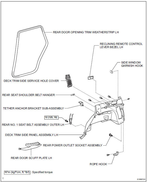
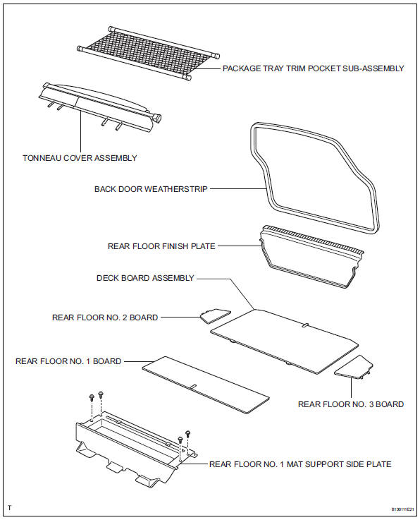
Components
Removal
- Disconnect cable from negative battery terminal
Caution:
Wait at least 90 seconds after disconnecting the cable from the negative (-) battery terminal to prevent airbag and seat belt pretensioner activation.
- Remove rear door scuff plate lh (see page ir-26)
- Remove rear door opening trim weatherstrip lh
- Remove package tray trim pocket subassembly
- Remove tonneau cover assembly
- Remove rear floor no. 1 Board
- Remove deck board assembly
- Remove rear floor no. 3 Board
- Remove rear floor no. 2 Board
- Remove rear floor no. 1 Mat support side plate (see page ir-31)
- Remove back door weatherstrip
- Remove rear floor finish plate (see page ir- 31)
- Remove reclining remote control lever bezel lh
- Remove tether anchor bracket subassembly
- Remove deck trim side panel assembly lh (w/ rear no. 2 Seat) (see page ir-32)
- Remove deck trim side panel assembly lh (w/o rear no. 2 Seat) (see page ir-32)
- Remove rear power outlet socket assembly
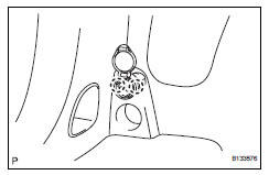
- Detach the 2 claws fittings and remove the socket.
Installation
- Install rear power outlet socket assembly
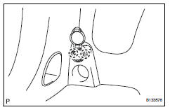
- Attach the 2 claw fittings to install the socket.
- Install deck trim side panel assembly lh (w/ o rear no. 2 Seat) (see page ir-52)
- Install deck trim side panel assembly lh (w/ rear no. 2 Seat) (see page ir-53)
- Install tether anchor bracket subassembly
- Install reclining remote control lever bezel lh
- Install rear floor finish plate (see page ir- 55)
- Install back door weatherstrip
- Install rear floor no. 1 Mat support side plate (see page ir-55)
- Install rear floor no. 2 Board
- Install rear floor no. 3 Board
- Install deck board assembly
- Install rear floor no. 1 Board
- Install tonneau cover assembly
- Install package tray trim pocket subassembly
- Install rear door opening trim weatherstrip lh
- Install rear door scuff plate lh (see page ir-59)
- Connect cable to negative battery terminal
 Center power outlet socket (for ac power supply)
Components
Removal
Disconnect cable from negative battery
terminal
Caution:
Wait at least 90 seconds after disconnecting the
cable from the negative (-) battery terminal to
prevent ai ...
 Maintenance
...
Other materials:
Security indicator light circuit
Description
When the transponder key is registered, the transponder key ecu indicates the
key registration condition
by lighting up, blinking or turning off the security indicator.
Wiring diagram
Inspection procedure
Perform active test by intelligent tester (security indicator light)
...
Terminals of ecu
Check combination meter assembly
Measure the voltage and resistance of the
connector.
Check instrument panel junction block (main body ecu)
Measure the voltage and resistance of the
connectors.
...
Lubrication system
On-vehicle inspection
Check engine oil level
Warm up the engine, stop the engine and wait for 5
minutes.
Check that the engine oil level is between the l and
f marks of the oil dipstick.
If low, check for leakage and add oil up to the f
mark.
Notice:
Do not add engine oil a ...
