
Toyota RAV4 (XA40) 2013-2018 Service Manual: Reassembly
Hint:
- Use the same procedures for the rh side and lh side.
- The procedures listed below are for the lh side.
- Install seat lock release band
- Install the band with nut.
Hint:
After installing the band, feed it through the seatback frame hole towards the rear of the vehicle.
- Install reclining lock release band
Hint:
Use the same procedures described for the lh side.
- Install seatback lock control cable assembly
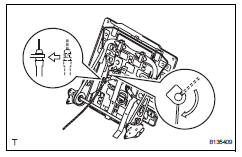
- Install the cable to the seatback frame as shown in the illustration.
- Install rear seat reclining inner cover lh
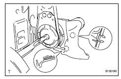
- Attach the 2 claws to install the inner cover.
- Install rear seat reclining inner cover rh
Hint:
Use the same procedures described for the lh side.
- Install rear no. 2 Seatback cover
Notice:
- Be careful not to damage the cover.
- When installing the hog rings, avoid wrinkling the cover.
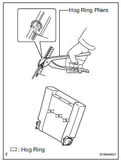
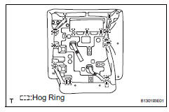
- Using hog ring pliers, install the seatback cover to the seatback pad with 3 new hog rings.
- Install the seatback cover (with pad) to the seatback frame.
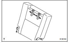
- Attach the 4 claws to install the 2 headrest supports.
- Using hog ring pliers, install 19 new hog rings.
- Install rear seatback board carpet assembly lh
- Pass the 2 release bands through the 2 holes in the seatback board carpet.
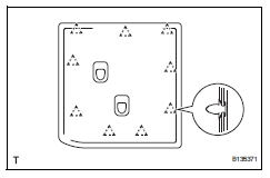
- Attach the 9 clips to install the carpet.
Hint:
Make sure that the release band is not inside the seatback board carpet.
- Install rear seatback lock control bezel
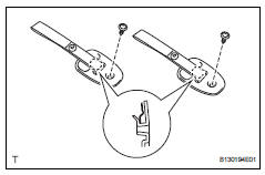
- Pass the 2 release bands through the 2 holes in the 2 bezels.
- Attach the 2 claws to install the 2 bezels.
- Install the 2 screws.
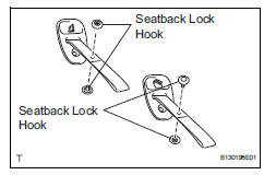
- Install the 4 seatback lock hooks.
- Install rear no. 2 Seat headrest assembly
- Install rear seat cushion wire subassembly
- Install the wire with the nut.
Torque: 18 n*m (184 kgf*cm, 13 ft.*Lbf)
- Install seat lock control cable assembly
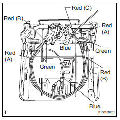
- Install the 5 cables to the seat cushion spring as shown in the illustration.
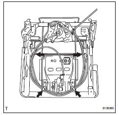
- Clamp the cables to the seat cushion spring with 4 new cable ties as shown in the illustration.
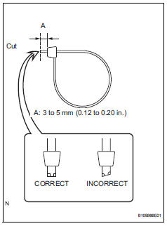
- Cut off the 2 cable ties, as shown in the illustration.
- Attach the 2 clamps of the cable tie to the seat cushion spring.
- Install rear no. 2 Seat cushion cover lh
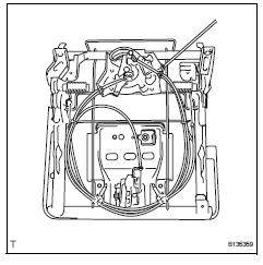
Notice:
- Be careful not to damage the cover.
- When installing the hog rings, avoid wrinkling the cover.
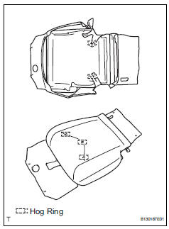
- Using hog ring pliers, install the seat cushion cover to the seat cushion pad with 5 new hog rings.
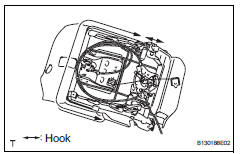
- Attach the hooks and install the seat cushion cover (with pad) to the seat cushion spring.
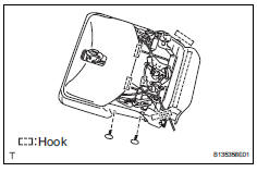
- Attach the 5 hooks.
- Install the 2 clips.
- Install rear no. 2 Seat inner belt assembly lh (see page sb-40)
- Remove rear no. 2 Seat cushion assembly
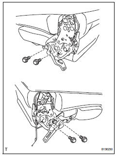
- Install the seat cushion to the seatback with the 4
bolts.
Torque: 42 n*m (428 kgf*cm, 31 ft.*Lbf)
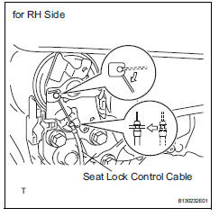
- Connect the seat lock control cable of the rh side to the seatback as shown in the illustration.
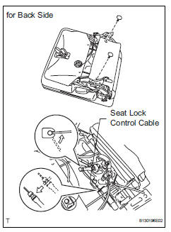
- Connect the seat lock control cable of the back side to the seat cushion as shown in the illustration.
- Close the seat cushion cover and install the 2 clips.
- Install no. 1 Rear seat reclining cover lh
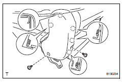
- Attach the 5 claws to install the cover.
- Install the 2 screws.
- Install no. 2 Rear seat reclining cover lh
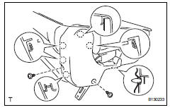
- Attach the clip and 5 claws to install the cover.
- Install the 2 screws.
 Disassembly
Hint:
Use the same procedures for the rh side and lh side.
The procedures listed below are for the lh side.
Remove no. 1 Rear seat reclining cover lh
Remove the 2 screws.
Using ...
 Installation
Hint:
Use the same procedures for the rh side and lh side.
The procedures listed below are for the lh side.
Install no. 2 Seat leg box protector
Attach the clip to install the pr ...
Other materials:
Power windows
Opening and closing the
power windows
The power windows can be
opened and closed using the
switches.
Operating the switch moves the
side windows as follows:
Closing
One-touch closing*
Opening
One-touch opening*
*: To stop the side window partway,
operate the switch in the opposite
direction. ...
Road test
Inspect set switch
Push the main switch on.
Drive at a desired speed (40 km/h (25 mph) or
higher).
Inspect "+" switch
Push the main switch button on.
Drive at a desired speed (40 km/h (25 mph) or
higher).
Press the control switch to -/set. ...
Data list / active test
Active test
Hint:
Performing the intelligent tester active test allows
relay, vsv, actuator and other items to be operated
without removing any parts. Performing the active
test early in troubleshooting is one way to save time.
The data list can be displayed during the active
test.
...
