Toyota RAV4 (XA40) 2013-2018 Service Manual: Shift lock system
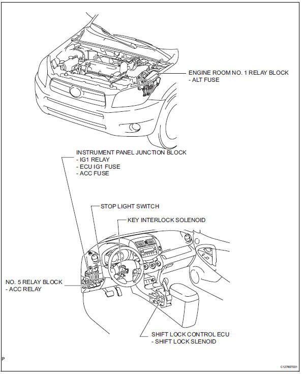
Parts location
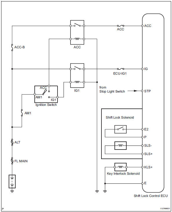
System diagram
On-vehicle inspection
- Check shift lock operation
- Move the shift lever to p.
- Turn the ignition switch off.
- Check that the shift lever cannot be moved to any position other than p.
- Turn the ignition switch on, depress the brake pedal and check that the shift lever can be moved to other positions
- Check shift lock release button operation
- When operating the shift lever with the shift lock release button pressed, check that the lever can be moved to any position other than p. If the operation cannot be performed as specified, check the shift lever assembly.
- Remove key interlock operation
- Turn the ignition switch on.
- Depress the brake pedal and move the shift lever to any position other than p.
- Check that the ignition switch cannot be turned off.
- Move the shift lever to p, turn the ignition switch off and check that the key can be removed. If the results are not as specified, inspect the shift lock control unit.
- Check shift lock control unit assembly
- Measure the voltage of the connector.
Hint:
Do not disconnect the shift lock control ecu connector.
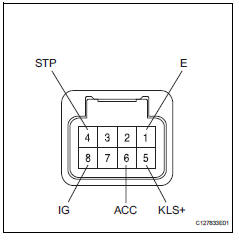
Standard voltage 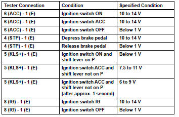
- The resistance of the connector.
Hint:
Do not disconnect the shift lock control ecu connector.
Standard resistance 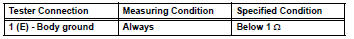
If the result is not as specified, replace the shift lock control ecu.
Inspection
- Inspect key interlock solenoid
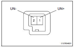
- Disconnect the solenoid connector.
- Connect the battery's positive (+) lead to terminal 1 (un+) and the battery's negative (-) lead to terminal 2 (un-).
Check that the operating noise of the solenoid can be heard.
If the result is not as specified, replace the solenoid.
 Valve body assembly
Components
Removal
Disconnect cable from negative battery
terminal
Caution:
Wait at least 90 seconds after disconnecting the
cable from the negative (-) battery terminal to
preven ...
 Transmission oil cooler
Components
Removal
Remove transmission oil cooler
*1: Disconnect the no. 3 Water by-pass hose from
the transmission oil cooler.
*2: Disconnect the no. 4 Water by-pass hose from
...
Other materials:
Voice settings
This screen is used for setting the voice command guidance
system.
Adjust the voice guidance volume
setting.
Set the voice recognition
prompts “high”, “low” or “off”.
Train voice recognition
Set the voice prompt interrupt
on/off.
Voice recognition tutorial
To re ...
Removal
(2006/01- )
Remove front wheel
Drain automatic transaxle fluid
Drain the automatic transaxle fluid for u140f (see
page ax-147).
Drain the automatic transaxle fluid for u241e (see
page ax-146).
Drain the automatic transaxle fluid for u151f (see
page ax-173).
Remove front axle hub nut ( ...
Steering gear
Components
Removal
Position front wheels facing straight
ahead
Disconnect cable from negative battery
terminal
Caution:
Wait at least 90 seconds after disconnecting the
cable from the negative (-) battery terminal to
prevent airbag and seat belt pretensioner activation.
...
