Toyota RAV4 (XA40) 2013-2018 Service Manual: Valve body assembly
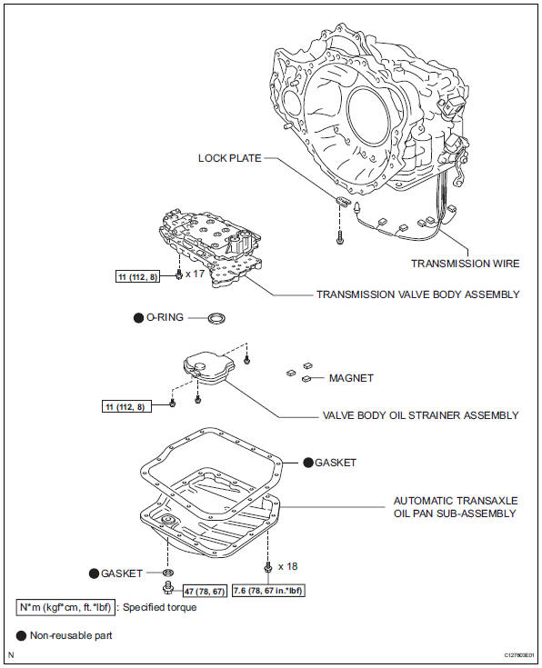
Components
Removal
- Disconnect cable from negative battery terminal
Caution:
Wait at least 90 seconds after disconnecting the cable from the negative (-) battery terminal to prevent airbag and seat belt pretensioner activation.
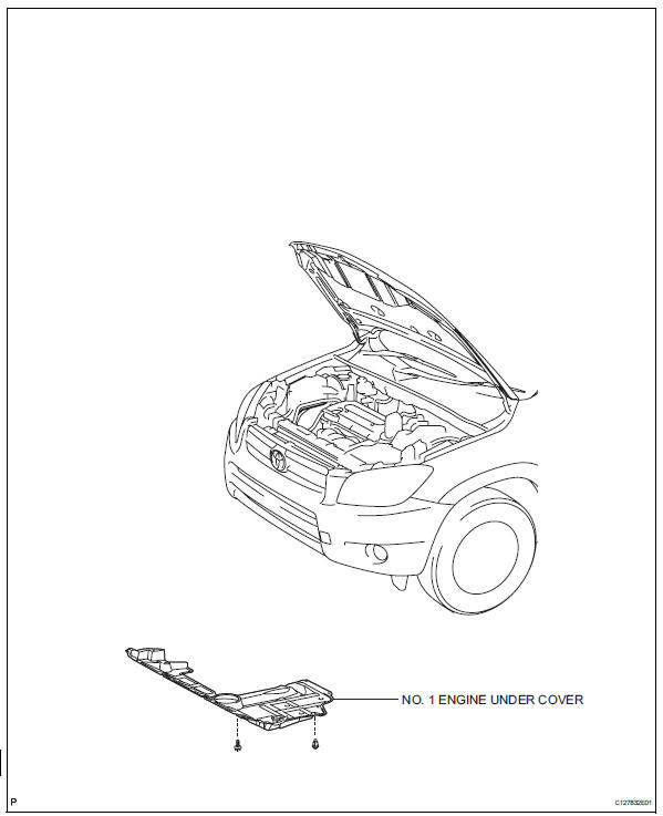
- Remove no. 1 Engine under cover
- Drain automatic transaxle fluid
- Remove the drain plug and gasket, and drain atf.
- Install a new gasket and the drain plug.
Torque: 47 n*m (479 kgf*cm, 35 ft.*Lbf)
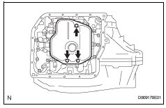
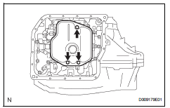
- Remove automatic transaxle oil pan subassembly
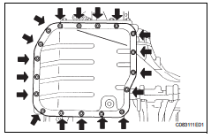
- Remove the 18 bolts, oil pan and gasket.
Notice:
Some fluid will remain in the oil pan. Carefully remove the oil pan sub-assembly.
- Remove the 3 magnets from the oil pan.
- Examine particles in the pan.
- Use the removed magnets to collect any steel
chips. Look carefully at the chips and particles
in the pan and on the magnet to anticipate what
type of wear you will find in the transaxle.
Steel (magnetic): bearing, gear and plate wear brass (non-magnetic): bush wear
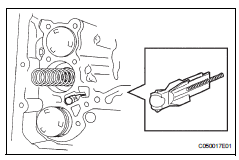
- Remove valve body oil strainer assembly
- Remove the 3 bolts and oil strainer.
Notice:
Be careful as some fluid will come out with the oil strainer.
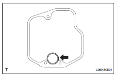
- Remove the o-ring from the oil strainer.
- Disconnect transmission wire
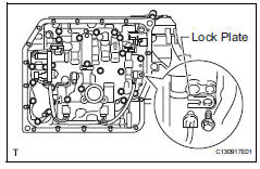
- Disconnect the 5 connectors.
- Remove the bolt and lock plate, and remove the atf temperature sensor.
- Remove transmission valve body assembly
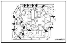
- Support the valve body and remove the 17 bolts and valve body.
Notice:
Be careful not to drop the check valve body, spring and accumulator piston.
- Remove the check ball body and spring.
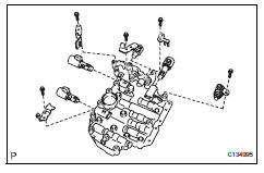
- Remove the 5 bolts, 4 plates and 5 shift solenoid valves.
Installation
- Install transmission valve body assembly
- Install the 5 shift solenoid valves with the 5 bolts and 4 plates.
Torque: 6.6 N*m (67 kgf*cm, 58 in.*Lbf) for bolt a 11 n*m (112 kgf*cm, 8 ft.*Lbf) for bolt b
Hint:
Each bolt length is indicated below.
Bolt length:
12 Mm (0.47 In.) For bolt a
45 Mm (1.77 In.) For bolt b
- Install the spring and check ball body.
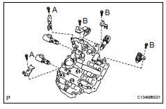
- Align the groove of the manual valve with the pin of lever
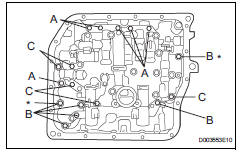
- Install the 17 bolts.
Torque: 11 n*m (112 kgf*cm, 8 ft.*Lbf)
Notice:
- Push the valve body against the accumulator piston spring and the check ball body to install it.
- Tighten the bolts marked by * in the illustration first temporarily because they are positioning bolts.
Hint:
Each bolt length is indicated below.
Bolt length:
25 Mm (0.984 In.) For bolt a
41 Mm (1.614 In.) For bolt b
45 Mm (1.771 In.) For bolt c
- Install transmission wire
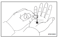
- Coat the o-ring of the temperature sensor with atf.
- Install the atf temperature sensor with the lock plate and bolt.
Torque: 6.6 N*m (67 kgf*cm, 58 in.*Lbf)
- Connect the 5 shift solenoid valve connectors.
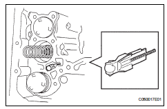
- Install valve body oil strainer assembly
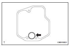
- Coat a new o-ring with atf.
- Install the o-ring to the oil strainer.
- Install the oil strainer with the 3 bolts.
Torque: 11 n*m (112 kgf*cm, 8 ft.*Lbf)
- Install automatic transaxle oil pan subassembly
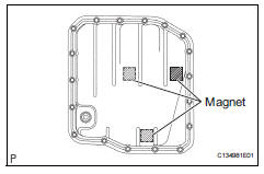
- Install the 3 magnets in the oil pan.
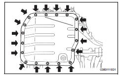
- Install a new gasket and oil pan with the 18 bolts.
Torque: 7.6 N*m (77 kgf*cm, 67 in.*Lbf)
- Install no. 1 Engine under cover
- Connect cable to negative battery terminal
- Add automatic transaxle fluid
Fluid type: toyota genuine atf ws
- Inspect transaxle fluid level
- Inspect the fluid level (see page ax-102).
- Perform reset memory
- Perform the reset memory procedures (a/t initialization) (see page ax-18).
 Transmission wire
Components
Removal
Disconnect cable from negative battery
terminal
Caution:
Wait at least 90 seconds after disconnecting the
cable from the negative (-) battery terminal to
preven ...
 Shift lock system
Parts location
System diagram
On-vehicle inspection
Check shift lock operation
Move the shift lever to p.
Turn the ignition switch off.
Check that the shift lever cannot be mov ...
Other materials:
Disassembly (2006/01- )
Remove front axle inboard joint boot no. 2
Clamp
One touch type:
using a screwdriver, remove the no. 2 Inboard joint
boot clamp, as shown in the illustration.
Claw engagement type:
using needle-nose pliers, remove the no. 2 Inboard
joint boot clamp, as shown in the illustra ...
Problem symptoms table
Hint:
Use the table below to help determine the cause of the
problem symptom. The potential causes of the symptoms
are listed in order of probability in the "suspected area"
column of the table. Check each symptom by checking the
suspected areas in the order they are listed. Re ...
Safety information for children
Observe the following precautions when children are in the vehicle.
Use a child restraint system appropriate for the child, until the
child becomes large enough to properly wear the vehicle’s seat
belt.
It is recommended that children sit in the rear seats to avoid
accidental
contact ...
