Toyota RAV4 (XA40) 2013-2018 Service Manual: Steering gear
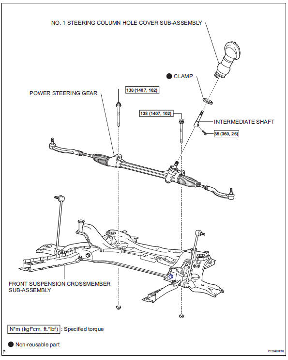
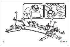
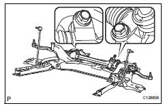
Components
Removal
- Position front wheels facing straight ahead
- Disconnect cable from negative battery terminal
Caution:
Wait at least 90 seconds after disconnecting the cable from the negative (-) battery terminal to prevent airbag and seat belt pretensioner activation.
- Remove front wheel
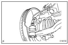
- Disconnect tie rod end sub-assembly lh
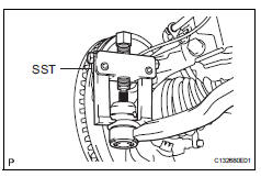
- Remove the cotter pin and castle nut.
- Using sst, disconnect the tie rod end from the steering knuckle.
Sst 09628-62011
Notice:
Do not damage the tie rod end dust cover.
- Disconnect tie rod end sub-assembly rh
Hint:
Use the same procedure for the rh side as for the lh side
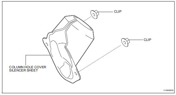
- Remove column hole cover silencer sheet
- Remove the floor carpet, 2 clips and column hole cover silencer.
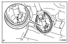
- Disconnect steering sliding yoke subassembly
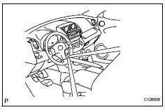
- Use a seat belt to fix the steering wheel in place to avoid breakage of the spiral cable.
- Place matchmarks on the sliding yoke of the steering intermediate shaft.
- Remove the bolt and disconnect the sliding yoke.
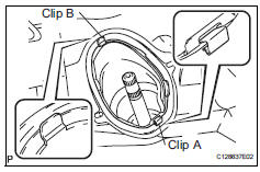
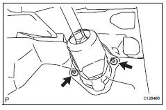
- Disconnect no. 1 Steering column hole cover sub-assembly
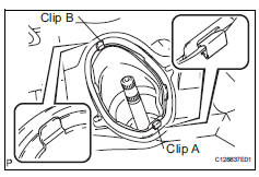
- Remove clip a, detach clip b from the body and disconnect the no. 1 Steering column hole cover.
Notice:
Do not damage clips a and b.
- Remove engine assembly with transaxle
- Remove the engine with transaxle (see page em- 98).
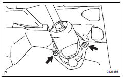
- Remove no. 1 Steering column hole cover sub-assembly
- Remove the clamp and disconnect the column hole cover from the steering gear.
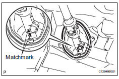
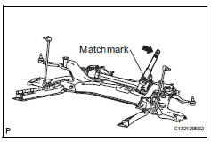
- Remove intermediate shaft
- Place matchmarks on the intermediate shaft of the steering gear.
- Remove the bolt and disconnect the steering intermediate shaft from the steering gear.
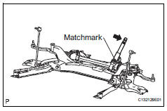
- Remove steering gear assembly
- Remove the 2 bolts, 2 nuts and steering gear from the suspension crossmember.
Notice:
Keep the nut from rotating while turning the bolt.
Installation
- Install steering gear assembly
- Install the steering gear onto the front suspension crossmember with the 2 bolts and 2 nuts.
Torque: 138 n*m (1407 kgf*cm, 102 ft.*Lbf)
Notice:
Keep the nut from rotating while turning the bolt.
- Install intermediate shaft
- Align the matchmarks and install the intermediate shaft onto the steering gear.
Torque: 35 n*m (360 kgf*cm, 26 ft.*Lbf)
- Install no. 1 Steering column hole cover sub-assembly
- Install the column hole cover onto the steering gear with a new clamp.
- Install engine assembly with transaxle
- Install the engine with transaxle (see page em-105).
- Install no. 1 Steering column hole cover sub-assembly
- Attach clip b onto the body portion and install the no. 1 Hole cover onto the body portion with clip a.
Notice:
Make sure that the lip portion of the no. 1 Hole cover is not damaged.
- Connect steering sliding yoke subassembly
- Align the matchmarks and install the sliding yoke onto the intermediate shaft.
Torque: 35 n*m (360 kgf*cm, 26 ft.*Lbf)
- Install column hole cover silencer sheet
- Install the column hole cover silencer sheet with the 2 clips.
- Install the floor carpet.
- Connect tie rod end sub-assembly lh
- Connect the tie rod end onto the steering knuckle with the castle nut.
Torque: 49 n*m (500 kgf*cm, 36 ft.*Lbf)
Notice:
If the holes for the clip are not aligned, tighten the nut up to 60Đ further.
- Install a new cotter pin.
- Connect tie rod end sub-assembly rh
Hint:
Use the same procedure for the rh side as for the lh side.
- Install front wheel torque: 103 n*m (1,050 kgf*cm, 76 ft.*Lbf)
- Connect cable to negative battery terminal
- Position front wheels facing straight ahead
- Inspect and adjust front wheel alignment
- Inspect and adjust the wheel alignment (see page sp-3).
 Eps warning light circuit
Description
If the power steering ecu detects a malfunction, the p/s warning light comes
on. At this time, the power
steering ecu stores a dtc in its memory.
Wiring diagram
Inspection proced ...
 Power steering ecu
Components
Removal
Disconnect cable from negative battery
terminal
Remove instrument panel sub-assembly
upper
Remove the instrument panel (see page ip-4).
Remove power steer ...
Other materials:
How to proceed with troubleshooting (2005/11-2006/01)
Hint:
Use these procedures to troubleshoot the air conditioning
system.
*: Use the intelligent tester.
Vehicle brought to workshop
Customer problem analysis and symptom check
Inspect battery voltage
Standard voltage:
11 to 14 v
If the voltage is below 11 v, recha ...
Blind Spot Monitor operation
â– Objects that can be detected while driving
The Blind Spot Monitor uses rear side radar sensors to detect the
following vehicles traveling in adjacent lanes and advises the driver
of the presence of such vehicles via the indicators on the outside
rear view mirrors.
Vehicles that are traveling ...
Fuel pump control circuit
Description
When the engine is cranked, the starter relay drive signal output from the
star terminal of the ecm is
input into the sta terminal of the ecm, and ne signal generated by the
crankshaft position sensor is also
input into the ne+ terminal. Thus, the ecm interprets that the engine is ...
