Toyota RAV4 (XA40) 2013-2018 Service Manual: Eps warning light circuit
Description
If the power steering ecu detects a malfunction, the p/s warning light comes on. At this time, the power steering ecu stores a dtc in its memory.
Wiring diagram
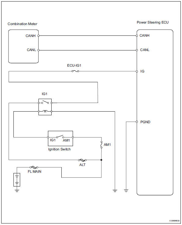
Inspection procedure
- Check for dtc
- Using the intelligent tester (with can vim), check for dtcs and confirm that there are no problems in the can communication system.
Ok: can dtcs are not output.


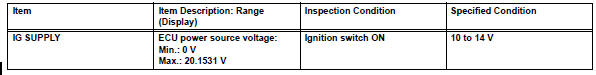
- Read value of intelligent tester (ig power supply)
- Connect the intelligent tester (with can vim) to the dlc3.
- Turn the ignition switch on and press the intelligent tester main switch on.
- Select the item "ig supply" in the data list and read the value displayed on the intelligent tester.
Main body ecu


- Inspect fuse (ecu-ig1)
- Remove the ecu-ig1 fuse from the instrument panel junction block.
- Measure the resistance of the fuse.
Ok:
below 1 

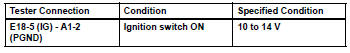
- Check wire harness (battery - power steering ecu and body ground)
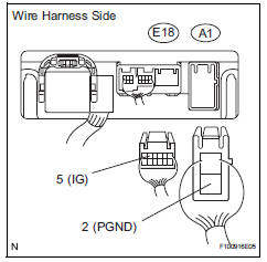
- Disconnect the a1 and e18 power steering ecu connector.
- Measure the voltage of the wire harness side connectors.
Standard voltage

- Perform active test by intelligent tester
- Connect the intelligent tester (with can vim) to the dlc3.
- Turn the ignition switch on and press the intelligent tester main switch on.
- Operate the intelligent tester according to the steps on the display and select the active test.
Combination meter

Ok: indicator comes on.

Replace power steering ecu
 Control module communication bus off
Description
The power steering ecu receives signals from the ecm and the skid control ecu
via the can
communication system.
Hint:
When 2 or more dtcs starting with [u] are output simul ...
 Steering gear
Components
Removal
Position front wheels facing straight
ahead
Disconnect cable from negative battery
terminal
Caution:
Wait at least 90 seconds after disconnecting the
cable f ...
Other materials:
If the engine will not start
If the engine will not start
even though correct starting
procedures are being
followed, consider
each of the following
points:
The engine will not start
even though the starter
motor operates normally
One of the following may be the
cause of the problem:
There may not be sufficient
fuel in the v ...
Bleeding
Hint:
If any work is performed on the brake system or if air in the
brake lines is suspected, bleed air from the brake system.
Notice:
Wash off brake fluid immediately if it comes in contact
with any painted surface.
Remove cowl top ventilator louver bracket lh
Detach the 6 claws and ...
Components
...
