Toyota RAV4 (XA40) 2013-2018 Service Manual: Diagnosis system
- Description
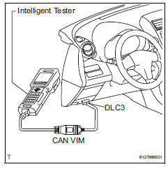
- Key reminder warning system data can be read through the data link connector 3 (dlc3) of the vehicle. When the system seems to be malfunctioning, use the intelligent tester (with can vim) to check for malfunctions and perform repairs.
- Check dlc3
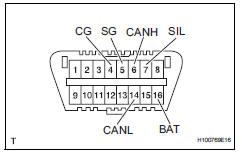
The vehicle's ecm uses iso 15765-4 communication protocol. The terminal arrangement of the dlc3 complies with iso 15031-03 and matches the iso 15765-4 format.
Notice:
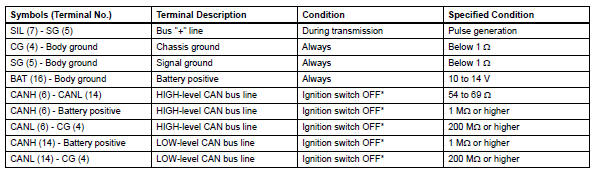
*: Before measuring the resistance, leave the vehicle as is for at least 1 minute and do not operate the ignition switch, other switches or doors.
If the result is not as specified, the dlc3 may have a malfunction. Repair or replace the harness and connector.
Hint:
Connect the cable of the intelligent tester (with can vim) to the dcl3, turn the ignition switch on and attempt to use the tester. If the display indicates that a communication error has occurred, there is a problem either with the vehicle or with the tester.
- If communication is normal when the tester is connected to another vehicle, inspect the dlc3 on the original vehicle.
- If communication is still not possible when the tester is connected to another vehicle, the problem may be in the tester itself. Consult the service department listed in the tester's instruction manual.
 Terminals of ecu
Check combination meter assembly
Measure the voltage and resistance of the
connector.
Check instrument panel junction block (main body ecu)
Measure the voltage and r ...
 Data list / active test
Read data list
Hint:
Using the intelligent tester's data list allows switch,
actuator and other item values to be read without
removing any parts. Reading the data list early in
troubleshoot ...
Other materials:
On-vehicle inspection
Hint:
When pressing the switch for 0.3 Seconds or less, the roof
glass moves but auto operation does not operate.
Check auto operation
Turn the ignition switch on.
When the roof glass is fully closed, press the slide
open switch for 0.3 Seconds or more. Check that
the roof glass au ...
Hitch
Trailer hitch assemblies have different weight capacities. Toyota recommends
the use of toyota hitch/bracket for your vehicle. For details,
contact your toyota dealer.
If you wish to install a trailer hitch, contact your toyota dealer.
Use only a hitch that conforms to the gross trailer weig ...
Test mode procedure
Test mode check
Hint:
When entering the test mode, the tire pressure
warning ecu sets all the test dtcs first. After
completing the test mode for each inspection item, the
dtcs that are determined normal by the tire pressure
warning ecu will be erased.
The dtcs for other inspec ...
