
Toyota RAV4 (XA50) 2019-2026 Owners Manual: Display contents
Following information is displayed on the multi-information display.
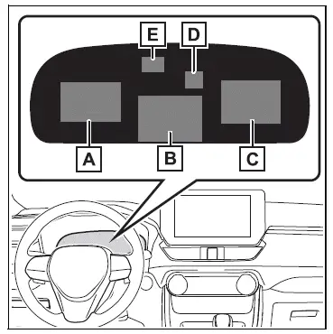
- Content display area (left)
- Content display area (center)
- Content display area (right)
- Driving support system information display area
When driving information support system is displayed on the content display area, the system operating state will not be displayed in this area.
- RSA (Road Sign Assist) display area (if equipped)
â– Content display area (center)
- Driving support system information display
- Settings display
- Warning message display
- Blank (No items)
â– Content display area (left/right)
- Fuel Economy
- Eco Driving Indicator
- Driving support system information display
- Navigation system-linked information display (if equipped)
- Audio system-linked display
- Drive information
- AWD operation status display (if equipped)
- Blank (No items)
â– The multi-information display is displayed when
The engine switch is in ON.
â– When changing driving mode
Background color of the multi-information display is changed following the selected driving mode.
â– Liquid crystal display
Small spots or light spots may appear on the display. This phenomenon is characteristic of liquid crystal displays, and there is no problem continuing to use the display.
WARNING
â– Caution for use while driving
- When operating the multi-information display while driving, pay extra attention to the safety of the area around the vehicle.
- Do not look continuously at the multi-information display while driving as you may fail to see pedestrians, objects on the road, etc. ahead of the vehicle.

 Meter control switches
: Change the screen
and move the cursor
: Change displayed
content and scroll up/down the screen
Press: Enter/Set
Press and hold: Reset/Display
customizable items/Display
the cursor
Move ...
Other materials:
Fuel injector
Components
Removal
Discharge fuel system pressure
Caution:
Discharge fuel system pressure
procedures must be performed before
disconnecting any part of the fuel system.
After performing the discharge fuel system
pressure procedures, pressure will remain in
the fuel line ...
Outside rear view mirrors
The rear view mirror's position
can be adjusted to
enable sufficient confirmation
of the rear view.
â– When using the outside rear
view mirrors in a cold weather
When it is cold and the outside rear
view mirrors are frozen, it may not
be possible to fold/extend them or
adjust the mirror surface. Rem ...
Disposal
Hint:
When scrapping a vehicle equipped with an srs or disposing
of the front passenger side knee airbag, be sure to deploy the
airbag first in accordance with the procedure described
below. If any abnormality occurs with the airbag deployment,
contact the service dept. Of toyota motor sales,
...
