Toyota RAV4 (XA50) 2019-2026 Owners Manual: Meter control switches
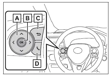
 : Change the screen
and move the cursor : Change displayed
content and scroll up/down the screen- Press: Enter/Set
Press and hold: Reset/Display customizable items/Display the cursor - Move the main meter and return to the previous screen
- Call sending/receiving and history display
Linked with the hands-free system, sending or receiving call is displayed.
For details regarding the hands-free system, refer to the "MULTIMEDIA OWNER'S MANUAL".
Changing the display
The multi-information display is operated using the meter control switches.
â– Changing the meter display type setting
The meter display type setting
can be changed on  .
.
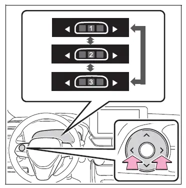
â– Changing the screen
Select items from the combination of 3 screens to display on each 3 content display areas.
Press  or
or
 of the meter
control switches to scroll the
screen.
â– Changing the display contents
Switches items displayed on each contents display area (left/center/right).
1. Press and hold  to display
the cursor on the content display
area (center).
2. Press  or
or
 to move the
cursor and select the content
display area.
3. Press  or
or
 to select the
items.
â– Items displayed in the content display area
Select to enable/disable items on the content display area (left/right).
1. Press and hold  to display
the cursor on the content display
area (center).
2. Press  or
or
 to move the
cursor and select the content
display area.
3. Contents display area (left):
Press  to display contents
list.
Contents display area (right):
Press  to display contents
list.
4. Press  or
or
 v to select the
items.
5. Press  to select
enable/disable items.
WARNING
â– Caution for use while driving
For safety, avoid operating the meter control switches while driving as much as possible, and do not look continuously at the multi-information display while driving.
Stop the vehicle and operate the meter control switches. Failure to do so may cause a steering wheel operation error, resulting in an unexpected accident.
 Display contents
Following information is displayed
on the multi-information
display.
Content display area (left)
Content display area (center)
Content display area (right)
Driving support system information
di ...
 Fuel Economy
Current fuel economy
Displays the driving range with
remaining fuel.
Average fuel economy
Displays the average fuel economy
since the function was reset or the average fuel economy after start ...
Other materials:
If the electronic key does
not operate properly (vehicles
with smart key system)
If communication between
the electronic key and vehicle
is interrupted or the electronic key cannot
be used because the battery
is depleted, the smart key
system and wireless remote
control cannot be used. In
such cases, the doors can
be opened and the engine
can be started by following
the procedur ...
Front suspension lower no. 1 Arm
Components
Removal
Remove front wheel
Remove hood sub-assembly
Remove the hood (see page ed-4).
Suspend engine assembly
Install the no. 1 And no. 2 Engine hangers with the
bolts as shown in the illustration.
Torque: 38 n*m (387 kgf*cm, 28 ft.*Lbf)
parts no.
...
Abnormal temperature inside
Description
The tire pressure warning valve and transmitter measures tire internal
temperature as well as tire
pressure, and transmits the information to the tire pressure monitor receiver
along with the transmitter id.
If the measured temperature is out of the specified range, the tire ...
