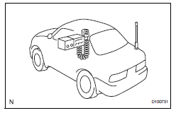
Toyota RAV4 (XA40) 2013-2018 Service Manual: For vehicles equipped with mobile communication systems

- Install the antenna as far away from the ecu and sensors of the vehicle electronic systems as possible.
- Install an antenna feeder at least 20 cm (7.87 In.) Away from the ecu and sensors of the vehicle electronic systems. For details about ecu and sensor locations, refer to the section of the applicable components.
- Keep the antenna and feeder separate from other wiring as much as possible. This will prevent signals of the communication equipment from affecting vehicle equipment and vice versa.
- Check that the antenna and feeder are correctly adjusted.
- Do not install a high-powered mobile communication system.
 Handling of hose clamps
Before removing the hose, check the clamp position
so that it can be reinstalled in the same position.
Replace any deformed or dented clamps with new
ones.
When reusing a hose, attach t ...
 For vehicles equipped with vehicle stability (vsc) system
Notices when using drum tester
Before beginning testing, disable the vsc. To
disable the vsc, turn the ignition switch off
and connect sst to terminals 12 (ts) and 4
(cg) of the dlc ...
Other materials:
Open in abs solenoid relay circuit
Description
The solenoid relay supplies power to the abs solenoid and trc solenoid.
After the ignition switch is turned on, the vehicle speed has reached 6 km/h (4
mph) and the solenoid is
determined to be normal by the initial check self-diagnosis, the relay switches
on. If any open or ...
Removal
Hint:
Use the same procedures for the rh side and lh side.
The procedures listed below are for the lh side.
Disconnect cable from negative battery
terminal
Caution:
Wait at least 90 seconds after disconnecting the
cable from the negative (-) battery terminal to
prevent airbag and ...
List screen operation
When a list screen is displayed, use the appropriate buttons to
scroll through the list.
How to scroll
Select to scroll to the next
or previous page.
Appears to the right of
titles, the complete titles are
too long for the display. Select
this button to scroll the title.
Turn th ...
