Toyota RAV4 (XA40) 2013-2018 Service Manual: Installation
- Install knock sensor
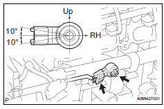
- Install the sensor with the nut.
Torque: 20 n*m (205 kgf*cm, 15 ft.*Lbf)
Notice:
Make sure that the knock sensor is in the correct position.
- Connect the sensor connector.
- Install intake manifold insulator
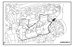
- install the intake manifold insulator onto the cylinder block.
- Install intake manifold
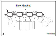
- Install a new gasket into the intake manifold.
- Install the intake manifold with the 5 bolts and 2 nuts.
Torque: 30 n*m (305 kgf*cm, 22 ft.*Lbf)
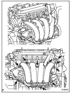
- Fit the union to check valve hose into the vacuum hose clamp.
- Install the wire harness clamp.
- Connect the camshaft timing oil control valve connector.
- Connect the union to check valve hose to the brake booster.
- Connect heater water outlet hose
- Install the heater water outlet hose to the water bypass pipe and heater radiator unit.
- Connect heater water inlet hose
- Install the heater water inlet hose to the cylinder head and heater radiator unit.
- Install the hose clamp.
- Install fuel tube
- Install fuel delivery pipe (see page fu-13)
- Install throttle body (see page es-413)
- Install air cleaner cap (see page es-413)
- Connect cable to negative battery terminal
- Add engine coolant (see page co-6)
- Check for engine coolant leakage (see page co-1)
- Check for fuel leakage (see page fu-14)
- Install no. 1 Engine cover (see page es-414)
 Inspection
Inspect knock sensor
Measure the resistance of the sensor.
Standard resistance
If the result is not as specified, replace the knock
sensor. ...
 Integration relay
On-vehicle inspection
Disconnect cable from negative battery
terminal
Caution:
Wait at least 90 seconds after disconnecting the
cable from the negative (-) battery terminal to
prevent airb ...
Other materials:
Unlock warning switch
Inspection
Inspect unlock warning switch assembly
Measure the resistance of the switch.
Standard resistance
If the result is not as specified, replace the switch
assembly.
Ecu power source circuit
Description
This circuit provides power to operate the transponder key ecu.
Wir ...
Tire inflation pressure
Make sure to maintain the
proper tire inflation pressure.
Tire inflation pressure
should be checked at least
once per month. However,
Toyota recommends that
tire inflation pressure be
checked once every two
weeks.
Checking the specified
tire inflation pressure
The recommended cold tire
inflation pr ...
Precaution
Precaution for vehicle with srs airbag and
seat belt pretensioner
Some operations in this section may affect the srs
airbags and seat belt pretensioner. Prior to
performing the corresponding operations, read the
srs airbag notice (see page rs-1).
Components
...
