Toyota RAV4 (XA40) 2013-2018 Service Manual: Removal
- Drain engine coolant (see page co-6)
- Disconnect cable from negative battery terminal
Caution:
Wait at least 90 seconds after disconnecting the cable from the negative (-) battery terminal to prevent airbag and seat belt pretensioner activation.
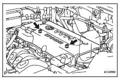
- Remove no. 1 Engine cover
- Remove the 2 nuts and engine cover.
- Remove air cleaner cap
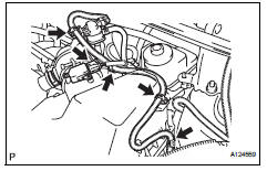
- Disconnect the mass air flow meter connector.
- Disconnect the purge vsv connector.
- Disconnect the 4 wire harness clamps.
- Disconnect the no. 2 Ventilation hose from the air cleaner hose.
- Disconnect the purge line hose from the clamp.
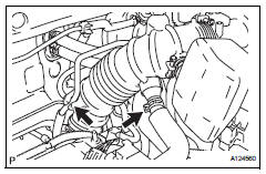
- Lock the no. 1 Air cleaner hose clamp, and then disconnect the no. 1 Air cleaner hose from the throttle body.
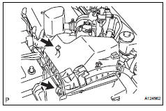
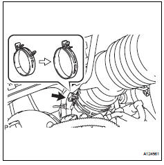
- Unfasten the 2 hook clamps, and then remove the air cleaner cap.
- Remove the air cleaner filter element from the air cleaner case.
- Remove throttle body
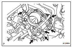
- Disconnect the purge line hose from the throttle body.
- Disconnect the water by-pass hose from the throttle body.
- Disconnect the no. 2 Water by-pass hose from the throttle body.
- Disconnect the no. 1 Throttle body hose from the throttle body
- Disconnect the throttle position sensor and control motor connector.
- Disconnect the wire harness clamp.
- Disconnect the fuel tube from the clamp.
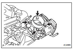
- Remove the 4 bolts, and then remove the fuel pipe support and throttle body.
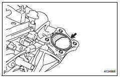
- Remove the gasket from the intake manifold
 On-vehicle inspection
Check throttle body
Check the throttle control motor operating sounds.
Turn the ignition switch on.
When pressing the accelerator pedal, check
the operating sound of the running mot ...
 Inspection
Inspect throttle body
Measure the resistance of the throttle control motor.
Standard resistance
If the result is not as specified, replace the throttle
body. ...
Other materials:
Compressor lock sensor circuit
Description
This sensor sends 1 pulse per engine revolution to the air conditioning
amplifier. If the ratio of the
compressor speed divided by the engine speed is smaller than a predetermined
value, the air conditioning
amplifier turns the compressor off, and the indicator blinks at appro ...
Reassembly
Install generator rotor assembly
Install the washer onto the generator rectifier end
frame.
Install the generator rotor onto the generator
rectifier end frame.
Using a 32 mm socket wrench and press, slowly
push the generator drive end frame onto the
generator ...
Front seat assembly (for power seat type lh side)
Components
...
