Toyota RAV4 (XA40) 2013-2018 Service Manual: Roof drip side finish moulding
Components
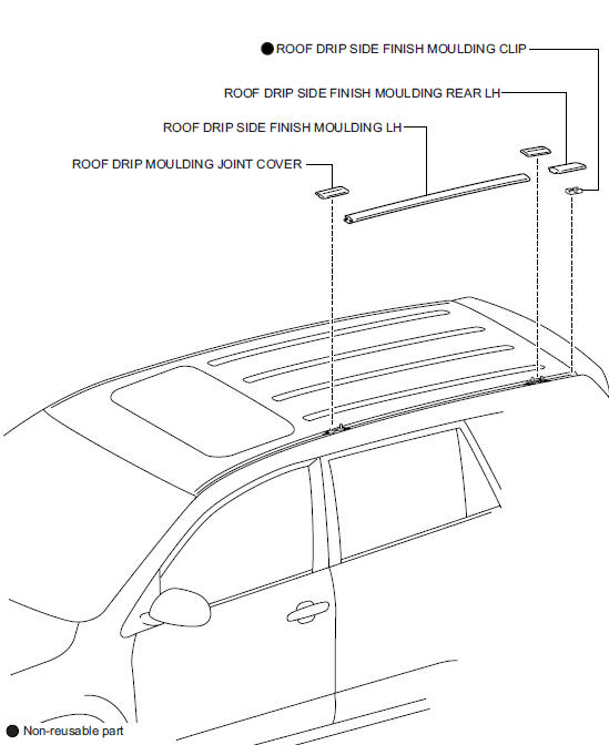
 Installation
Hint:
Use the same procedures for the rh side and lh side.
The procedures listed below are for the lh side.
Install front pillar cover sub-assembly upper lh
Attach the 3 clips to install ...
 Removal
Hint:
Use the same procedures for the rh side and lh side.
The procedures listed below are for the lh side.
Remove roof drip side finish moulding lh
Remove the 2 roof drip moulding j ...
Other materials:
Compressor circuit
Description
When the a/c switch is turned on, the magnetic clutch on signal is sent from
the air conditioning
amplifier. Then the mg clt relay turns on to operate the magnetic clutch.
Wiring diagram
Inspection procedure
Perform active test by intelligent tester (a/c mag clutch)
C ...
General maintenance (2005/11-2006/01)
General notes
Maintenance requirements vary depending on the
country.
Check the maintenance schedule in the owner's
manual supplement.
Following the maintenance schedule is mandatory.
Determine the appropriate time to service the vehicle
using either miles driven or time elapsed ...
Ignition coil
Components
Removal
Disconnect cable from negative battery terminal
Caution:
Wait at least 90 seconds after disconnecting the
cable from the negative (-) battery terminal to
prevent airbag and seat belt pretensioner activation.
Remove no. 1 Engine cover (see page es-410)
Remove i ...
