Toyota RAV4 (XA40) 2013-2018 Service Manual: Motor rotation angle sensor malfunction
![]()
Description
The motor rotation angle sensor detects the motor rotation angle and sends this information to the power steering ecu.
![]()
Wiring diagram
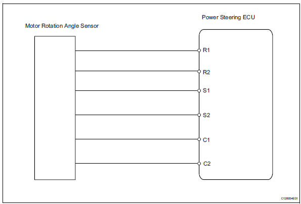
Inspection procedure
- Check connector connection condition
- Check the installation condition of the motor rotation angle sensor connector.
Ok: motor rotation angle sensor connector is securely connected to the power steering ecu.
Result 


- reconfirm dtc
- Reinstall motor rotation angle sensor connector.
- Check for dtc.
Ok: dtc is not output.
Result 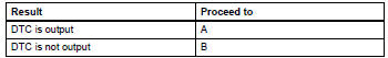

- Read value of intelligent tester (motor rotation angle sensor)
- Connect the intelligent tester (with can vim) to the dlc3.
- Turn the ignition switch on and press the intelligent tester main switch on.
- Select the items "motor rotate" in the data list
and read the value displayed on the intelligent tester.
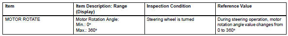
Ok: during steering operation, motor rotation angle value changes from 0 to 360ĐĽ/b>


Replace power steering ecu
 Motor terminal voltage malfunction
Description
The power steering ecu supplies the current to the power steering motor
through the motor circuit.
Wiring diagram
Inspection procedure
Read value of intelligent tester ( ...
 Ecu malfunction
Description
Inspection procedure
If the power steering ecu detects these dtcs, it will shut off the motor
relay circuit (built into the power
steering ecu) and stop power assist. However, pow ...
Other materials:
Reassembly
Hint:
When installing the ornament plate and emblem, heat the
radiator grille, ornament plate and emblem using a heat light.
Standard heating temperature
Notice:
Do not heat the emblem base and emblem excessively.
Install radiator grille emblem
Attach the 4 claws to install the radi ...
Diagnosis system
Description
Key reminder warning system data can be read
through the data link connector 3 (dlc3) of the
vehicle. When the system seems to be
malfunctioning, use the intelligent tester (with can
vim) to check for malfunctions and perform repairs.
Check dlc3
The vehi ...
Identification information
Vehicle identification and serial numbers
Vehicle identification number
The vehicle identification number is stamped on the
vehicle identification number plate and on the
certification label, as shown in the illustrations.
Vehicle identification number plate
Certification label ...
